Parallel Adder and Subtractor:
Parallel Adder and Subtractor which consists of three categories, namely, n Bit Parallel Adder,Binary Parallel Adder and n Bit Parallel Subtractor.
n Bit Parallel Adder:
We have seen, a single full-adder is capable of adding two one-bit numbers and an input carry. In order to add binary numbers with more than one bit, additional full-adders must be employed. A n Bit Parallel Adder can be constructed using number of full adder circuits connected in parallel.
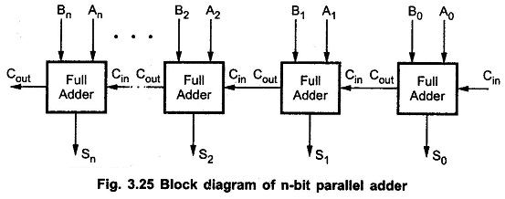
Fig. 3.25 shows the block diagram of n Bit Parallel Adder using number of full-adder circuits connected in cascade, i.e. the carry output of each adder is connected to the carry input of the next higher-order adder.
It should be noted that either a half-adder can be used for the least significant position or the carry input of full adder is made 0 because there is no carry into the least significant bit position.
Binary Parallel Adder (IC 74LS83 /73LS283):
Many high-speed adders available in integrated-circuit form utilize the look-ahead carry or a similar technique for reducing overall propagation delays. The most common is a 4-bit parallel adder IC (74LS83 / 74283) that contains four inter connected full-adders and the look-ahead carry circuitry needed for high-speed operation.
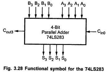
The 7483 and 74283 are a TTL medium scale integrated (MSI) circuit with same pin configuration. Fig. 3.28 shows the functional symbol for the 74LS283 4-bit parallel adder. The inputs to this IC are two 4-bit numbers, A3 A2 A1 A0 and B3 B2 B1 B0, and the carry, Cin0, into the LSB position. The outputs are the sum bits S3 S2 S1 S0, and the carry, Cout3, output of the MSB position.
Two or more parallel-adder blocks can be connected (cascaded) to accommodate the addition of larger binary numbers.
n Bit Parallel Subtractor:
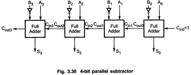
The subtraction of binary numbers can be done most conveniently by means of complements. Remember that the subtraction A-B can be done by taking the 2’s complement of B and adding it to A. The 2’s complement can be obtained by taking the 1’s complement and adding one to the least significant pair of bits. The 1’s complement can be implemented with inverters and a one can be added to the sum through the input carry, as shown in the Fig. 3.30.