Locus Diagram of Parallel RLC Circuit:
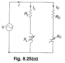
(a) Variable XL – Locus plots are drawn for parallel branches containing RLC elements in a similar way as for series circuits. Here we have more than one current locus. Consider the Locus Diagram of Parallel RLC Circuit shown in Fig. 8.25(a). The quantities that may be varied are XL, XC, RL and RC for a given voltage and frequency.
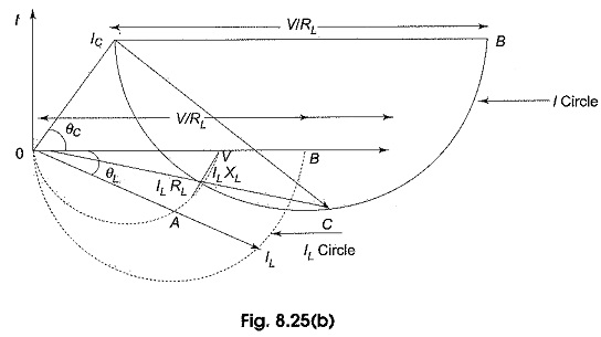
Let us consider the variation of XL from zero to ∞. Let OV shown in Fig. 8.25(b), be the voltage vector, taken as reference. A current, IC, will flow in the condenser branch whose parameters are held constant and leads V by an angle θC = tan-1 (XC/RC), when XL = 0, the current IL, through the inductive branch is maximum and is given by V/RL and it is in phase with the applied voltage.
When XL is increased from zero, the current through the inductive branch IL decreases and lags V by θL = tan-1 XL/RL as shown in Fig. 8.25(b). For any value of IL, the ILRL drop and ILXL drop must add at right angles to give the applied voltage. These drops are shown as OA and AV respectively. The locus of IL is a semicircle, and the locus of ILRL drop is also a semicircle. When XL = 0, i.e. IL is maximum, IL coincides with the diameter of its semicircle and ILRL drop also coincides with the diameter of its semi-circle as shown in the figure; both these semicircles are shown with dotted circles as OILB and OAV respectively.
Since the total current is IC + IL. For example, a particular value of IC and IL the total current is represented by OC on the total current semicircle. As XL is varied, the locus of the resultant current is therefore, the circle IC CB as shown with thick line in the Fig. 8.25(b).
(b) Variable XC – A similar procedure can be adopted as outlined above to draw the locus plots of I1 and I when XC is varying while RL, RC, XL, V and f are held constant. The curves are shown in Fig. 8.25(c).
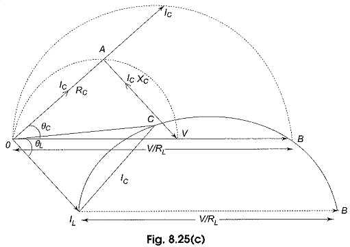
OV presents the voltage vector, OB is the maximum current through RC branch when XL = 0; OIL is the current through the RL branch lagging OV by an angle θL = tan-1 CL/RL.
As XC is increased from zero, the current through the capacitive branch IC decreases and leads V by θC = tan-1 XC/RC. For a particular IC, the resultant current I = IL + IC and is given by OC. The dotted semicircle OICB is the locus of the IC, thick circle ILCB is the locus of the resultant current.
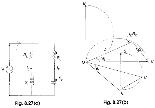
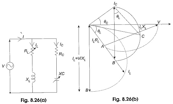
(c)Variable RL – The locus of current for the variation of RL in Fig. 8.26(a) is shown in Fig. 8.26(b). OV represents the reference voltage, OILB represents the locus of IL and ICCB represents the resultant current locus. Maximum IL = V/XL is represented by OB.
(d)Variable RC – The locus of currents for the variation of RC in Fig. 8.27(a) is plotted in Fig. 8.27(b) where OV is the source voltage and semicircle OAB represents the locus of IC. The resultant current locus is given by BCIL.