Parallel Magnetic Circuit:
We have seen that a series magnetic circuit carries the same flux and the total mmf required to produce a given quantity of flux is the sum of the mmf’ s for the separate parts. In a Parallel Magnetic Circuit, different parts of the circuit are in parallel. For such circuits the Kirchhoff s laws, in their analogous magnetic form can be applied for the analysis. Consider an iron core having three limbs A, B and C as shown in Fig. 10.31(a).
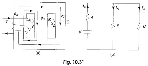
A Coil with N turns is arranged around limb A which carries a current I amperes. The flux produced by the coil in limb A. ΦA is divided between limbs B and C and each equal to ΦA/2.
The reluctance offered by the two parallel paths is equal to the half the reluctance of each path (Assuming equal lengths and cross sectional areas). Similar to ICirchhoff s current law in an electric circuit, the total magnetic flux directed towards a junction in a magnetic circuit is equal to the sum of the magnetic fluxes directed away from that junction.
Accordingly ΦA = ΦB + ΦC or ΦA – ΦB – ΦC = 0. The electrical equivalent of the above circuit is shown in Fig. 10.31(b). Similar to Kirchhoff s second law, in a closed magnetic circuit, the resultant mmf is equal to the algebraic sum of the products of field strength and the length of each part in the closed path. Thus applying the law to the first loop in Fig. 10.31(a), we get
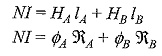
The mmf across the two parallel paths is identical.
Therefore NI is also equal to
![]()