Parallel Operation of Synchronous Generator:
We already know that synchronous machine connected to infinite bus-bars. Parallel Operation of Synchronous Generator of two finite size will be considered, which is the way large practical size generators are used. In a power system the generators are connected to the nodes of a grid composed of a network of transformers and transmission lines. A national level grid may comprise even hundreds of generators and hundreds of kilometres of the transmission line. The grid formation is dictated by reasons of reliability (continuity of supply) and by investment and operating economics of the power plant.
Parallel Operation of Synchronous Generator shown in Figure 8.62 shows two synchronous generators along with their primemovers to be operated in parallel. After the two generators are brought to their respective synchronous speeds and their field currents adjusted to give nearly equal terminal voltages, switch S is closed in accordance with the synchronizing procedure. Active and reactive powers, supplied to the common load by each generator, are controlled respectively by their primemover throttles and field currents.

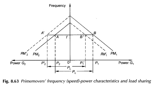
The active power-sharing between paralleled generators is dependent upon the droop of the frequency (speed)-power characteristics of the primemovers and their governors. Theses characteristics are nearly linear for small changes in the operating (rated) frequency and power as shown in Fig. 8.63. These characteristics can be slided up or down by adjustment of the set points of their governors. Drooping frequency-power characteristics are essential for proper loading between generators and the adjustment thereof.
For the solid-line characteristics shown in Fig. 8.63, load PL = AB at frequency f (rated) is shared as P1 and P2 such that P1 + P2 = PL. In order to increase the load on G2 and to correspondingly reduce the load on G1, the frequency-power characteristic of G2 must be raised by adjustment of the governor setting, and to keep the frequency constant the characteristic of G1 must be simultaneously lowered. It is seen from the figure that with this adjustment, PL = P′1 + P′2 where (P1 — P’1) = (P’2 — P2) = ΔP, the load amount which is transferred from G1 to G2 by adjustment of governors. It also follows that if the governor setting of only one of the primemovers is adjusted, the system frequency would change. During the process of governor setting adjustment, the system undergoes load-frequency transient which would soon die out (provided the governors are properly damped) and steady load-frequency conditions established with new load sharing.
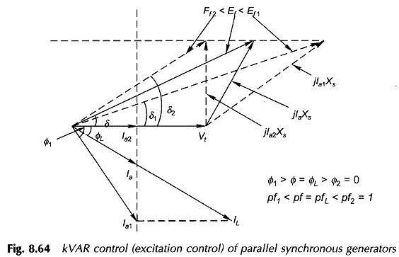
Changes in excitation of Parallel Operation of Synchronous Generator affect the terminal voltage and reactive-power loading with active power sharing remaining unchanged (primemover governor settings are not disturbed). This was clarified with respect to a single machine connected to infinite bus-bars. For the system of two generators as in Fig. 8.62, assume that the two generators are identical, their primemover governors are adjusted for equal load sharing in parallel operation of synchronous generator and their excitations are equal; so that they operate with identical currents and power factors (i.e. both active and reactive powers are equally shared). The phasor diagram under these operating conditions, identical for each generator, is shown in Fig. 8.64 in thick line.
KVAR Control of Parallel Synchronous Generators:
For the given total load and equal sharing of real load, let the excitation of G1 be now increased and that of G2 simultaneously reduced in such a manner as to keep the terminal voltage unchanged. Each generator, therefore, behaves as if it is connected to infinite bus-bars, i.e., Ef sin δ will remain constant. With active power on each generator fixed (at half the total), the projection of generator (each) current on Vt (active current component) will also remain constant and as a result the power factor of G1 goes down and that of G2 improves (figure is drawn for upf).
Thus G1 supplies more kVAR to load and G2 supplies an equal amount less. This is how reactive load sharing between generators can be controlled. If, however, the excitation of only one of the generators is raised (or lowered), the terminal voltage will increase (or decrease) while this generator shares a larger (or smaller) part of load kVAR. For raising (lowering) the terminal voltage without modifying the kVAR sharing, the excitation of both the generators must be raised (or lowered).
Excitation is automatically controlled by voltage regulators acting on the field circuits of generators. All that is needed to be done is to change the set-points of voltage regulators.
The prime mover governor and generator voltage regulator control loops are assumed independent in the above. They are, however, weakly coupled because of losses in generators. Independence of control loops is a good working assumption.