Synchronous Generator with Distributed Winding:
Synchronous Generator with Distributed Winding – It may be seen from Eq. (5.7) that the flux/pole is limited by the machine dimensions and the peak flux density which cannot exceed a specified value dictated by saturation characteristic of iron. Therefore, for inducing an emf of an appropriate value in a practical machine (it may be as high as 11√3 to 37/√3 kV/phase), a large number of coil turns are needed and it is not possible to accommodate all these in a single slot-pair. Furthermore, it may be also noticed that with one coil/pole pair/phase, i.e. one slot/pole/phase, the periphery of the stator is far from being fully utilized.
![]()
It is, therefore, natural to create more slots/pole/phase (SPP) on the stator periphery. In a practical machine with S slots distributed uniformly round the stator periphery,
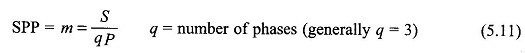
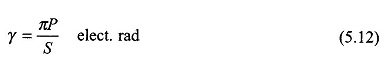
Figure 5.17 illustrates a 2-pole, 3-phase machine synchronous generator with distributed windings with m = 3. The angle between adjacent slots is
The winding of phase a in this machine has three coils (11′, 22′ and 33′) which are placed in three slot-pairs distributed in space with an angular separation of γ elect. rad. The total angle σ = mγ occupied by the phase winding along the armature periphery is called the phase spread. Such a winding is referred to as the distributed winding. Since the machine is always wound with identical coils, the sinusoidal emfs induced in coils 11′, 22′ and 33′ have the same rms value (E) but have a progressive time phase difference of γ because these coils are uniformly distributed in space.
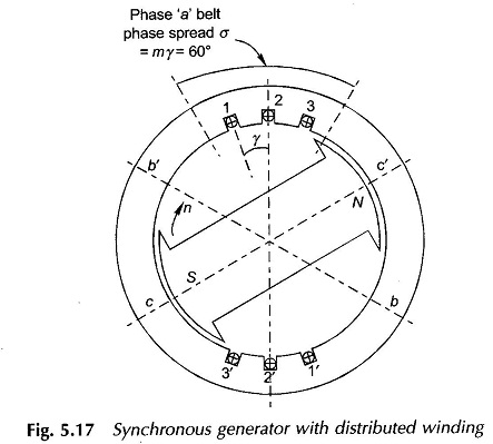
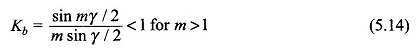
These coils are series connected to yield the phase voltage Ea which is the phasor sum of the coil emf’s as shown in Fig. 5.18. It is observed from this figure that because of distribution, the rms phase voltage is less than the algebraic sum of the rms coil voltages. This reduction ratio called the breadth factor (also distribution factor) is to be determined now, for the general case of SSP = m.
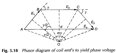
It is easily seen that in Fig. 5.18 the coil emf phasors form sides of a regular polygon, the centre of whose circumscribing circle is construction-ally located in the diagram. The phase voltage Ea is given by the resultant phasor (AD in Fig. 5.18). The breadth factor is then defined as
![]()
From the geometry of Fig. 5.18
AB = 2 OA sin γ/2
It is seen from Eqs (5.11) and (5.12) that
The induced phase emf for a distributed winding is obtained by multiplying Eq. (5.10) by kb. Thus
![]()
where
Nph = total turns (in series) per phase