EMF Equation of AC Winding:
The B-wave of a EMF Equation of AC Winding synchronous machine (in general multi-polar) assumed sinusoidal is drawn in Fig. 5.15 and a single full-pitched coil (coil-side space separation π rad (180°) elect.) is shown in cross-sectional form. The B-wave moves towards left with a speed of ω elect. rad/s or ωm mech. rad/s. At the origin of time the coil-sides are located in the interpolar region where the full pole flux links the coil. At any time t the coil has relatively moved by
![]()
to the right of the B-wave. The B-wave can be expressed as
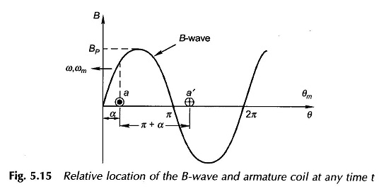
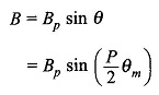
where Bp = peak flux density
Since the flux is physically spread over the mechanical angle, the flux Φ linking the coil can be computed by integrating over the mechanical angle. Thus
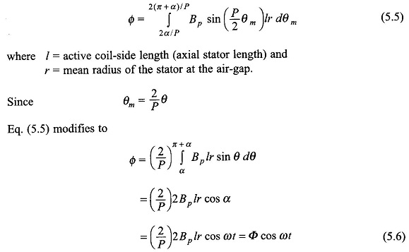
It is, therefore, seen that the flux linking the coil varies sinusoidally and has a maximum value of
The negative sign in Eq. (5.9) (e = –dλ/dt) accounts for the fact that the assumed positive direction of emf and current in the coil aa’ of Fig. 5.2 produces flux along the coil axis causing positive flux linkages. In case of the transformer the positive direction of emf was assumed such as to cause a current which would produce negative flux linkages and therefore the induced emf law used was e = + dλ/dt.
It may be observed that the spatial flux density wave upon rotation causes time-varying flux linkages with the coil and hence the production of EMF Equation of AC Winding, an effect which is produced by a fixed-axis time-varying flux in a transformer. The time-variation factor is introduced by rotation causing the phenomenon of electromechanical energy conversion which is not possible in a transformer with fixed-axis time-varying flux.
The rms value of emf induced in the coil from Eq. (5.9) is
![]()
which is the same result as in a transformer except for the fact that Φ here is the flux/pole.
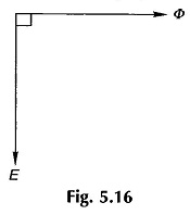
It may be observed from Eqs (5.6) and (5.9) that the sinusoidally varying flux linking the coil (represented by the phasor Φ) leads the sinusoidallly varying emf (represented by the phasor E) by 90°.
The phasor relationship is illustrated by the phasor diagram of Fig. 15.6. This is in contrast to the transformer case wherein the flux phasor lags the emf phasor by 90°. This difference is caused by the negative sign in the induced emf of Eq. (5.9) while a positive sign was used for the transformer.