Two layer Winding of Transformer:
One important and commonly used way of neatly arranging the end connection of coils in a winding is to place two coil-sides per slot. Each coil then has one coil-side in the bottom half of one slot and the other coil-side in the top half of another slot (one pole pitch away for full-pitched coils). Such a winding is known as a Two layer Winding of Transformer.
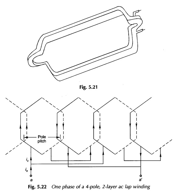
All the coils of a Two layer Winding of Transformer are of similar shape so that these can be wound separately and then placed in the slots. The end connections at each end of such a coil are given an involute kink so that the coil-sides can be conveniently placed in the bottom of one slot and top of the other. A formed two-layer, mutli-turn coil is shown in Fig. 5.21.
The winding connections of a two-layer winding are best illustrated by means of a developed winding diagram which imagines that the stator has been cut and laid out flat. One phase of a 4-pole, two-layer lap winding is shown in Fig. 5.22.
The upper layer is indicated by a thick line and the lower layer by a dotted line and both are drawn side-by-side in the diagram. This figure illustrates the simplest case of 4-poles with 1 slot/pole/phase. The four coils could be series connected or various series-parallel connections could be employed.
In Fig. 5.22 the four coils of one phase are connected in parallel in two series groups of two coils each. Obviously the phase current ia and the conductor current ic are related as ic = ia/2.