What is Summation Transformer?
Summation devices are employed to compare the relaying quantities derived from the currents in the three phases of the primary circuit. The effectiveness of the comparison of the derived relaying quantities may be considered in terms of the effective ratio of the primary currents under comparison, such as at the two ends of a feeder. Summation transformer are employed for converting 3-phase quantities into single-phase quantities.
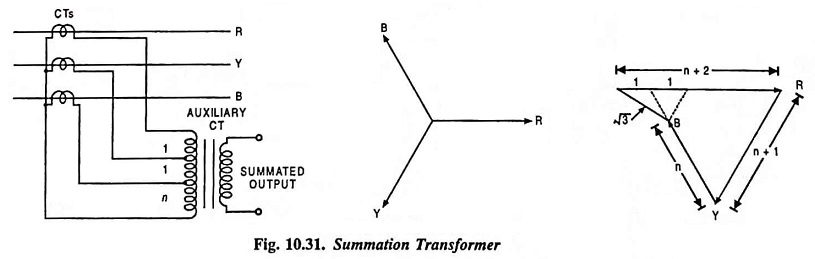
The basic arrangement summation transformer is shown in Fig. 10.31. The three line CTs are connected to the primary of an auxiliary CT (summation transformer), as illustrated in the figure. Each line CT energizes a different number of turns on the primary of the auxiliary CT and the resulting single-phase output appears across the secondary.
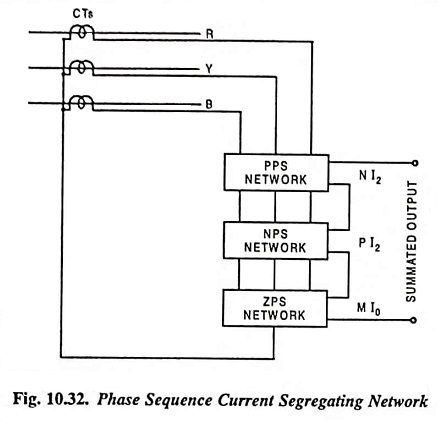
In case the device is to be employed for unbalanced conditions in the system and due to fault conditions to operate the relays properly, it is preferable to convert the unbalanced currents into positive, negative and zero sequence components. A simple arrangement of the phase sequence current segregating network is shown in Fig. 10.32. The summated output will be according to fault conditions. Summation devices have their limitations because of loss of discrimination due to condensation of information.
The output ampere-turns from any summation device may be expressed in terms of symmetrical components in the form MI0 + NI1 + PI2 where M, N and P depend on the choice of summated quantities. The ratio of the compared quantities, for example, at the end of a protected feeder say A and B is given as
![]()
The values of M, N and P depend on the summation device and on the phase affected by the fault. The ideal conditions assume that the current transducers are linear in response and so also the summation devices.
The effective output from the secondary winding of the summation transformer having primary turn ratio 1 : 1 : n
(Fig. 10.31) is given as
![]()
If this is to be expressed in symmetrical components, it becomes
![]()
This defines the constants M, N and P for the reference phase fault conditions i.e., ground fault, double line to ground fault etc. For the faults on the phases other than the reference phase R, the N and P should be multiplied by a and a2 operators respectively, to define the appropriate output.
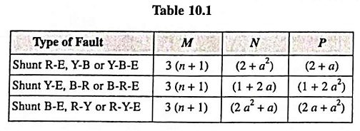
The values of M, N and P for various types of faults referred to the phase R for summation transformer having turn ratio 1 : 1 : n are given below in tabular form [Table 10.1].
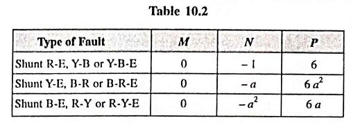
In case of phase sequence network filters, the recent studies show that the preferred values of M : N : P are 0 : -1 : 6 for reference phase R. For faults on other phase, the value are given below in tabular form [Table 10.2]
Summation transformer is a simpler summation device and has less burden while sequence network filters are more versatile.