Phase Conversion in Transformer:
Three Phase to Two Phase Conversion Transformer (Scott-T transformer or Scott Connection):
Phase conversion from three to two phase is needed in special cases, such as in supplying 2-phase electric arc furnaces.
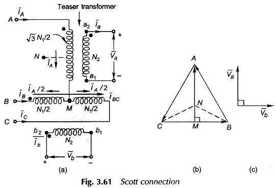
The concept of 3/2-phase conversion follows from the voltage phasor diagram of balanced 3-phase supply shown in Fig. 3.61(b). If the point M midway on VBC could be located, then VAM leads VBC by 90°. A 2-phase supply could thus be obtained by means of transformers; one connected across AM, called the teaser transformer and the other connected across the lines B and C. Since VAM = (√3/2)VBC, the transformer primaries must have √3 N1/2 (teaser) and N1 turns; this would mean equal voltage/turn in each transformer.
A balanced 2-phase supply could then be easily obtained by having both secondaries with equal number of turns, N2. The point M is located midway on the primary of the transformer connected across the lines B and C. The connection of two such transformers, known as the Scott connection, is shown in Fig. 3.61(a), while the phasor diagram of the 2-phase supply on the secondary side is shown in Fig. 3.61(c).
The neutral point on the 3-phase side, if required, could be located at the point N which divides the primary winding of the tertiary in the ratio 1 : 2 (refer Fig. 3.61(b)).
Load Analysis:
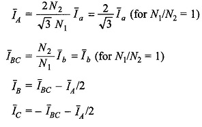
If the secondary load currents are Ia and Ib, the currents can be easily found on the 3-phase side from Fig. 3.61(a).
The corresponding phasor diagram for balanced secondary side load of unity power factor is drawn in Fig. 3.62 from which it is obvious that the currents drawn from the
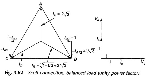
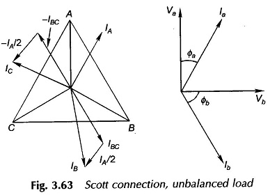
3-phase system are balanced and cophasal with the star voltages. The phasor diagram for the case of an unbalanced 2-phase load is drawn in Fig. 3.63.
Three to Single Phase Converter Transformer:
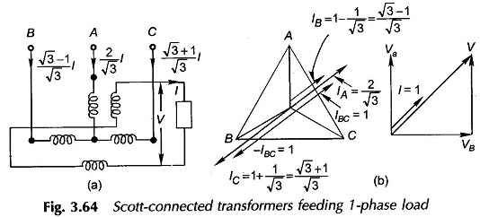
A single-phase power pulsates at twice the frequency, while the total power drawn by a balanced 3-phase load is constant. Thus a 1-phase load can never be transferred to a 3-phase system as a balanced load without employing some energy-storing device (capacitor, inductor or rotating machine). Suitable transformer connections can be used in distributing a 1-phase load on all the three phases though not in a balanced fashion. For large 1-phase loads, this is better than allowing it to load one of the phases of a 3-phase system. A variety of transformer connections are possible. Figure 3.64(a) shows how Scott-connected transformers could be used for this purpose and Fig. 3.64(b) shows the corresponding phasor diagram.
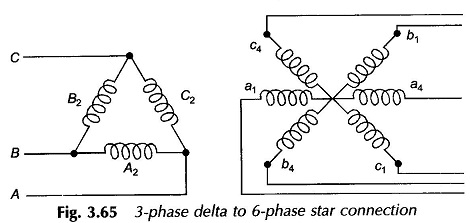
Three Phase to Six Phase Conversion Transformer:
Each secondary phase is divided into two equal halves with polarity labeling as in Fig. 3.47. Six-phase voltages (characteristic angle 360°/6 = 60°) are obtained by means of two stars in phase opposition, each star being formed from three respective half-windings as shown in Fig. 3.65. This connection is employed in rectifiers and thyristor circuits where a path for the dc current is needed.