Three Phase Transformer Connections:
In generation, transformation, transmission and utilization of electric energy it can be shown that it is economical to use the three-phase system rather than the single-phase. For Three Phase Transformer Connections, three single-phase transformers are needed. Two arrangements are possible: a bank of three single-phase transformers or a single three-phase transformer with the primary and secondary of each phase wound on three legs of a common core. The Three Phase Transformers unit costs about 15% less than that of a bank and furthermore, the single unit occupies less space. There is little difference in reliability, but it is cheaper to carry spare stock of a single-phase rather than a Three Phase Transformers. In underground use (mines) a bank of single-phase units may be preferred as it is easier to transport these units.
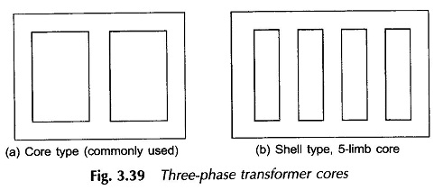
The bank also offers the advantage of a derated open-delta operation when one single-phase unit becomes inoperative. Reduced cost being an overweighing consideration, it is common practice to use a three-phase transformer unit. In a three-phase bank the phases are electrically connected but the three magnetic circuits are independent. In the more common three-phase, 3-limb core-type transformer (Fig. 3.39(a)), the three magnetic circuits are also linked. Where delinking of the magnetic circuits is desired in a three-phase unit, a 5-limb shell type transformer could be used (Fig. 3.39(b)).
A variety of connections are possible on each side of a 3-phase transformer (single unit or bank). The Three Phase Transformer Connections could be connected in star, delta, open-delta or zig-zag star. Each of the Three Phase Transformers could have two windings or may have autoconnection. Further, certain types of connections require a third winding known as tertiary.
Labelling of Transformer Terminals:
Terminals on the HV side of each phase will be labelled as capital letters A, B, C and those on the LV side will be labelled as small letters a, b, c. Terminal polarities are indicated by suffixes 1 and 2 with 1’s indicating similar polarity ends and so do 2’s. Labelling of terminals is illustrated in Fig. 3.40 for phase a. Assuming the transformer to be ideal, VA2A1 (voltage of terminal A2 with respect to A1) is in phase with Va2a1 and IA is in phase with Ia.
![]()
Star Star Transformer Connection (Y/Y):
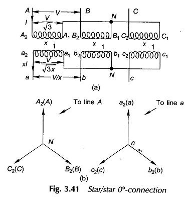
Star connection is formed on each side by connecting together phase winding terminals suffixes 1 as in Fig. 3.41(a). The phasor diagram is drawn in Fig. 3.41(b) from which it is easily seen that the voltages of the corresponding phases (and therefore of the corresponding lines) are in phase. This is known as the 0°-connection. The letters within brackets on the phasor diagram indicate the lines, to which the terminals are If the winding terminals on secondary side are reversed, the 180°-connection is obtained.
It is also observed from Fig. 3.41 that if the phase transformation ratio is x : 1, the line transformation (line-to-line voltages, line currents) the ratio is also x : 1.
Delta Delta Transformer Connection (Δ/Δ):
Figure 3.42(a) shows the delta/delta connection and the corresponding phasor diagram is given in Fig. 3.42(b). The sum of voltages around the secondary delta must be zero; otherwise delta, being a closed circuit, means a short circuit. With polarities indicated on the primary and secondary sides, voltages Va2a1,Vb2b1 and Vc2c1 add to zero as per the phasor diagram if the delta is formed by connecting a1b2, b1c2 and c1a2. It is easily seen from the phasor diagram that the primary and secondary line voltages are in phase so it is the 0°-connection. However, if the secondary leads a, b, c are taken out from the delta nodes a1b2, b1c2, c1c2, the secondary voltages are in phase opposition to the primary voltages can be visualized from the phasor diagram of Fig. 3.42(b). This is the 180°-connection.
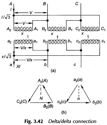
It is also seen from Fig. 3.42(a) that if the phase transformation ratio is x : 1, the transformation ratio for line quantities is also x : 1.
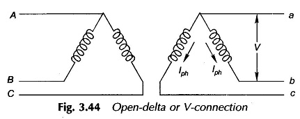
In the delta/delta connection if one of the Three Phase Transformer Connections is disconnected, the resulting connection is known as open-delta. Supposing the b-phase transformer in Fig. 3.42(a) is removed, and the open-delta is excited from balanced 3-phase supply, then it easily follows from the phasor diagram of Fig. 3.42(b) that the voltage Vb2b1 = Vbc, does not change as it equals -(Vca + Vab); thus the voltages on the secondary side still remain balanced 3-phase. The open-delta connection supplying a balanced load is shown in Fig. 3.44. If the maximum allowable secondary phase current is Iph, the transformer can handle VA of
![]()
Thus the open-delta connection has a VA rating of 1/√3 = 0.58 of the rating of the normal delta/delta connection.
Star Delta Transformer Connection (Y/Δ):
Star connection is formed on primary side by connecting together 1 suffixed terminals; 2 suffixed terminals being connected to appropriate lines; the delta is formed by connecting c1a2,a1b2 and b1c2 with the lines connected to these junctions being labelled as a, b and c respectively as shown in Fig. 3.45(a). The phasor diagram of Three Phase Transformers is drawn in Fig. 3.45(b). It is seen from the phasor diagram on the delta side that the sum of voltages around delta is zero. This is a must as otherwise closed delta would mean a short circuit. It is also observed from the phasor diagram that phase a to neutral voltage (equivalent star basis) on the delta side lags by — 30° to the phase-to-neutral voltage on the star side; this is also the phase relationship between the respective line-to-line voltages. This connection, therefore, is known as — 30°-connection.
The + 30°-connection follows from the phasor diagram of Fig. 3.46(a) with the corresponding connection diagram as in Fig. 3.46(b).
Similarly ± 90°-connections are also possible in the star/delta connection by relabeling the delta side lines. For example for + 90° connection relabel c —> a, b —> c and a —> b. Reader may work out relabeling for — 90° connection.
In Indian and British practices ± 30°-connections are employed. The American practice is to use ± 90°-connections.
It follows from Fig. 3.45(a) that if the phase transformation ratio of the star/delta connection is x : 1, the line transformation ratio in magnitude is √3 : x/1.

Delta Star Transformer Connection (Δ/Y):
This connection is simply the interchange of primary and secondary roles in the star/ delta connection. One just interchanges capital and small letter suffixings in Figs 3.45 and 3.46. Of course what was the — 30°-connection will now be the + 30°-connection and vice versa. If the phase transformation ratio is x : 1 (delta/star), the transformation ratio for line quantities will be (x/√3) : 1.
Delta Zig Zag Star Connection:
The winding of each phase on the star side is divided into two equal halves with labelling as in Fig. 3.47. Each leg of the star connection is formed by using halves from two different phases. The phasor diagram for this connection is given in Fig. 3.48 from which the connection diagram easily follows. Obviously it is the 0°-connection. Reversal of connections on the star side gives us the 180°-connection.
Phase transformation = x : 1

Star/Zig-zag Star:
The Three Phase Transformer Connections is indicated by the phasor diagram of Fig. 3.49.

![]()
Phase Groups:
Various Three Phase Transformer Connections with the same phase shift are grouped together. Thus there are Group I (0°), Group II (180°), Group III (30°) and Group IV (— 30°).