Circuit Connections for Producing a Vectrogram and Lissajous Pattern:
This test instrument combines a keyed colour bar generator with an oscilloscope and is used for alignment and testing the colour section of a TV receiver. The amplitude and phase of the chrominance signal represents the colour saturation and hue of the scene. This information can also be displayed on the oscilloscope screen in the form of Lissajous pattern. The resultant display is called a vectrogram.
A separate colour bar generator with a conventional CRO can be used to produce a vectrogram. The necessary circuit connections and the resulting pattern are shown in Fig. 8.19.
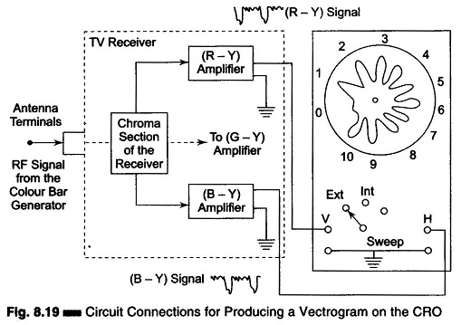
With the gated colour bar generator connected at the input terminals of the receiver, serrated (R – Y) and (B – Y) video signals become available at corresponding control grids of the colour picture tube. These two outputs are connected to the vertical and horizontal inputs of the CRO. Since both (R – Y) and (B – Y) inputs are interrupted sine waves and have a phase difference of 90° with each other, the resultant Lissajous pattern is in the basic form of a circle which collapses towards the centre during the serrations in the signals.
Assuming ideal input signal waveforms, the formation of a vectrogram is given in Fig. 8.20.
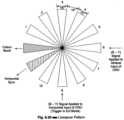
Since there are 10 colour bursts, the pattern displays ten petals. The horizontal sync and colour burst do not appear in the display because these are blanked out during retrace intervals.
The position of each petal represents the phase angle of each colour in the colour bar pattern.
For example, petal 1, 3, R – Y, 6, B – Y and 10 (G – Y) correspond to angles 30°, 90°, 180°, and 360° respectively.
Vectroscope usually have an overlay sheet on the scope screen, marked with segment numbers and corresponding phase angles. This enables the user to identify different colours and interpret the size and shape of each petal.
In actual practice, the top of (R – Y) and (B – Y) bar signals do not have sharp corners and the resultant pattern is somewhat feathered and rounded at the periphery. This is depicted in the actual pattern shown on the oscilloscope screen in Fig. 8.20.
Rounding of corners and feathering occurs due to limited HF response and non-zero rise-time of the amplifier in a colour bar generator and oscilloscope.
With a vectogram display, chroma troubles can be ascertained and servicing expedited.
For example the loss of an (R – Y) signal causes the vectrogram to be H-line only. Similarly, the absence of (B – Y) results in a single vertical line on the screen. Any change of the receiver colour control will alter the amplitude of both (R – Y) and (B – Y) signals and cause the diameter of the pattern to change.
The receiver fine tuning affects the size and shape of the reproduced pattern. Proper fine tuning produces the largest and best shaped vectrogram.
If some of the petals are longer than others, non-linear distortion is indicated. If the petal tops are flattened, some circuit overloading is occurring in the receiver.
It is also possible to check for defective colour stages, mistuned band-pass amplifier, misadjusted circuitry in the sub-carrier oscillator section and inoperative colour stages.
Vectroscopes are also used in TV recording studios to adjust the white balance of various cameras and to monitor colour signals during recording.