RX Meter Circuit in Measuring Instruments:
An RX Meter Circuit in Measuring Instruments is used to measure the separate resistive and reactive components of a parallel Z network. It is especially useful in the design of RF tank circuits but can be used with any parallel “Z”. The basic circuit of a typical RX meter is shown in Fig. 10.16.
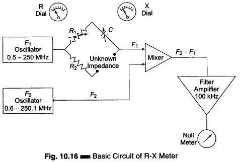
As shown in RX Meter Circuit shown in Fig. 10.16, there are two variable frequency oscillators that track each other at frequencies 100 kHz apart. The output of a 0.5 – 250 MHz oscillator, F1 is fed into a bridge. When the impedance network to be measured is connected across one arm of the bridge, the equivalent parallel resistance and reactance (capacitive or inductive) unbalances the bridge and the resulting voltage is fed to the mixer. The output of the 0.6 – 250.1 MHz oscillator F2, tracking 100 kHz above F1, is also fed to the mixer.
This results in a 100 kHz difference frequency proportional in level to the bridge unbalance. The difference frequency signal is amplified by a filter amplifier combination and is applied to a null meter. When the bridge resistive and reactive controls are nulled, their respective dials accurately indicate the parallel impedance components of the network under test. For example, if balance is achieved with 50 Ω of resistance and 300 Ω of reactance, the network under test has the same values.