Q Meter:
The overall efficiency of coils and capacitors intended for RF applications is best evaluated using the Q value. The Q Meter is used to measure some electrical properties of coils and capacitors. The Q Meter Working Principle is based on series resonance; the voltage drop across the coil or capacitor is Q times the applied voltage (where Q is the ratio of reactance to resistance, XL/R). If a fixed voltage is applied to the circuit, a voltmeter across the capacitor can be calibrated to read. Q directly.
At resonance XL= XC and EL= IXL, EC = IXC, E = I R
where
- E – applied voltage
- EC – capacitor voltage
- EL – inductive voltage
- XL – inductance reactance
- XC – capacitive reactance
- R – coil resistance
- I – circuit current
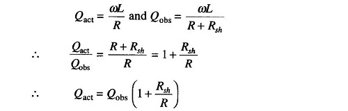
Therefore
![]()
From the above equation, if E is kept constant the voltage across the capacitor can be measured by a voltmeter calibrated to read directly in terms of Q.
Q Meter Circuit Diagram:
A practical Q meter circuit diagram is shown in Fig. 10.7.
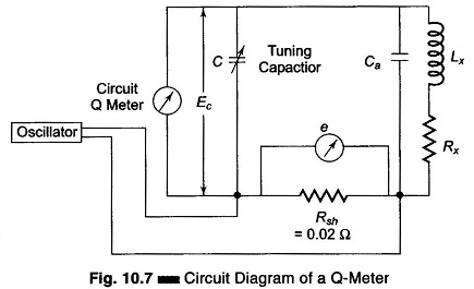
The wide range oscillator, with frequency range from 50 kHz to 50 MHz, delivers current to a resistance Rsh having a value of 0.02 Ω. This shunt resistance introduces almost no resistance into the tank circuit and therefore represents a voltage source of a magnitude e with a small internal resistance. The voltage across the shunt is measured with a thermocouple meter. The voltage across the capacitor is measured by an electronic voltmeter corresponding to Ec and calibrated directly to read Q.
The oscillator energy is coupled to the tank circuit. The circuit is tuned to resonance by varying C until the electronic voltmeter reads the maximum value. The resonance output voltage E, corresponding to Ec, is E = Q x e, that is, Q = E/e. Since e is known, the electronic voltmeter can be calibrated to read Q directly.
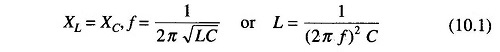
The inductance of the coil can be determined by connecting it to the test terminals of the instrument. The circuit is tuned to resonance by varying either the capacitance or the oscillator frequency. If the capacitance is varied, the oscillator frequency is adjusted to a given frequency and resonance is obtained. If the capacitance is pre-setted to a desired value, the oscillator frequency is varied until resonance occurs. The Q reading on the output meter must be multiplied by the index setting or the “Multiply Q by” switch to obtain the actual Q value. The inductance of the coil can be calculated from known values of the coil frequency and resonating capacitor (C).
The Q indicated is not the actual Q, because the losses of the resonating capacitor, voltmeter and inserted resistance are all included in the measuring circuit. The actual Q of the measured coil is somewhat greater than the indicated Q. This difference is negligible except where the resistance of the coil is relatively small compared to the inserted resistance Rsh.
1. Factors that May Cause Error:
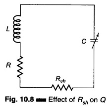
1. At high frequencies the electronic voltmeter may suffer from losses due to the transit time effect. The effect of Rsh is to introduce an additional resistance in the tank circuit, as shown in Fig. 10.8.
where
- Qact = actual Q
- Qobs = observed Q
To make the Qobs value as close as possible to Qact, Rsh should be made as small as possible. An Rsh value of 0.02 – 0.04 Ω introduces negligible error.
2. Another source of error, and probably the most important one, is the distributed capacitance or self capacitance of the measuring circuit. The presence of distributed or stray capacitances modifies the actual Q and the inductance of the coil. At the resonant frequency, at which the self capacitance and inductance of the coil are equal, the circuit impedance is purely resistive—this characteristic can be used to measure the distributed capacitance.
One of the simplest methods of determining the distributed capacitance (Cs) of a coil involves the plotting of a graph of 1/f2 against C in picofarads.
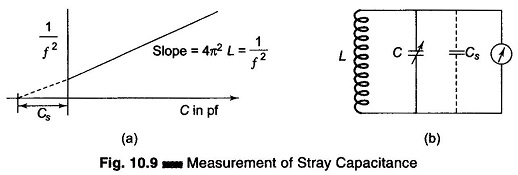
The frequency of the oscillator in the Q meter is varied and the corresponding value of C for resonance is noted. 1/f2 is plotted against C in picofarads, as shown in Fig. 10.9(a). The straight line produced to intercept the X-axis gives the value of Cs, from the formula given on the next page. The value of the unknown inductance can also be determined from the equation.
![]()
and

Therefore

If

Another method of determining the stray or distributed capacitance (Cs) of a coil involves making two measurements at different frequencies. The capacitor C of the Q meter is calibrated to indicate the capacitance value. The test coil is connected to the Q meter terminals, as shown in Fig. 10.9(b)
The tuning capacitor is set to a high value position (to its maximum) and the circuit is resonated by varying the oscillator frequency. Suppose the meter indicates resonance and the oscillator frequency is found to be f1 Hz and the capacitor value to be C1.
The oscillator frequency, of the Q-meter is now increased to twice the original frequency, that is, f2 = 2f1, and the capacitor is varied until resonance occurs at C2. The resonant frequency of an LC circuit is given by

Therefore, for the initial resonance condition, the total capacitance of the circuit is (C1 + Cs) and the resonant frequency equals

After the oscillator and the tuning capacitor are varied for the new value of resonance, the capacitance is (C2 + Cs), therefore

But f2 = 2f1.
Therefore
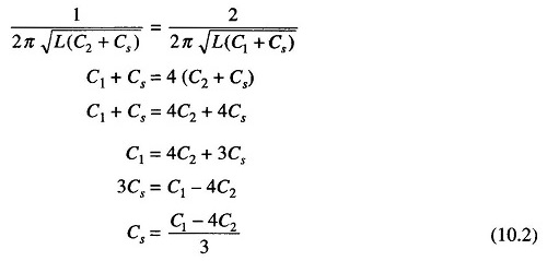
The distributed capacitance can be calculated using the equation above.
2. Impedance Measurement Using Q Meter:
An unknown impedance can be measured using a Q meter, either by series or shunt substitution method. If the impedance to be measured is small, the former is used and if it is large the later method is used.
In the Q meter method of measurement of Z, the unknown impedance Zx is determined by individually determining its components Rx and Lx. The technique utilizes an LC tank of a Q meter, L being an externally connected standard coil.
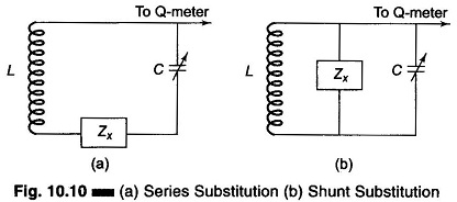
Figure 10.10(a) shows the method of series substitution while Fig. 10.10(b) shows the shunt substitution method.
Referring to Fig. 10.10(a), the unknown impedance is shorted or otherwise not connected and the tuned circuit is adjusted for resonance at the oscillator frequency. The value of Q and C are noted. The unknown impedance is then connected, the capacitor is varied for resonance, and new values Q’ and C’ are noted.
From part 1, we have
![]()
From part 2, we have
![]()
Subtracting Eq. (10.4) from Eq. (10.3), we have
Since R’ = R + Rx, Rx = R’ – R, where R is the resistance of the auxiliary coil.

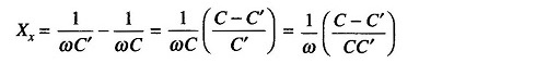
The unknown impedance Zx can be calculated from the equation
![]()
A positive value of Xx indicates inductive reactance and a negative value indicates capacitive reactance.
If Zx is considerably greater than XL, the unknown impedance is shunted across the coil and the capacitor, as shown in Fig. 10.10(b).
Yx represents the shunt admittance of the unknown impedance. It consists of two shunt elements, conductance Gx and susceptance Bx. In this method, Yx is disconnected and the capacitor C is tuned to the resonant value. At the oscillator frequency, the values of Q and C are noted. With Yx connected, the capacitor is tuned again for resonance at the oscillator frequency and the new values Q’ and C’ are noted.
Hence
![]()
and
![]()
also

Therefore

The accuracy with which the reactance can be determined by the method of substitution is quite high. Error may mainly be because
- C’ cannot be accurately determined since the resonance curve may be flat due to additional resistance, and
- The stray inductance associated with the tuning capacitor causes errors at VHF.
The accuracy with which the resistance component of the unknown impedance is obtained is poor. If the losses in the unknown impedance are too small to introduce any change in the Q, the substitution method is quite satisfactory.
The substitution method can also be used for measuring the losses of the coil. It is not satisfactory for measuring the losses of an air-dielectric capacitor, since they are too small to be detected by this method.
3. Measurement of Characteristic Impedance (Z0) of a Transmission Line Using Q Meter:
Figure 10.11(a) shows a series substitution method for determining the characteristic impedance of a transmission line and Fig. 10.11(b) shows a shunt or parallel method of substitution for the same purpose.
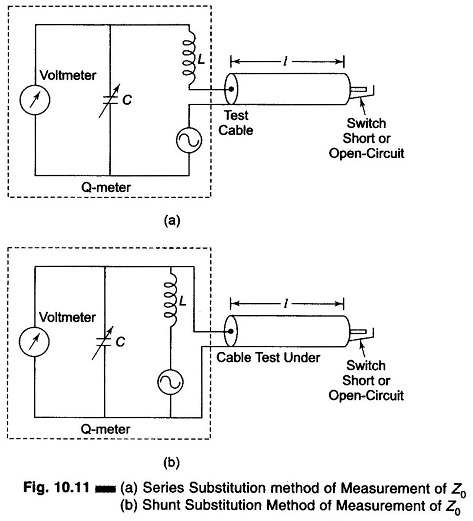
In Fig. 10.11(a), the transmission line or cable under test is tuned for series resonance. Since the input impedance is low, the method of series substitution can be used to determine Z0 = R0 +jX0 for the transmission line, as explained in the previous section.
The reactance/unit length of the line is the total reactance divided by the length l.
Series resonance occurs when the line is short-circuited and the line length is an even multiple of a λ/4 and when open-circuited an odd multiple of λ/4.
Parallel resonance occurs when the line is short-circuited and the length is an odd multiple of λ/4, or open-circuited it is an even multiple of λ/4.
4. Measurement of Q by Susceptance Method:
The coil under test is connected in series with a calibrated low loss variable capacitor. With the use of the meter as an indicator, the circuit is tuned for resonance to the oscillator frequency, by tuning the variable capacitor to a value Cr, a shown in Fig. 10.12(a). The capacitor is then detuned to a value Cb on the low capacitance side of resonance at which the meter reading falls to 70.7% of the resonant voltage. Next, the capacitor is set on the higher capacitance side of resonance to a value Ca, where the voltmeter deflection again drops to 70.7% of the resonant voltage, as shown in Fig. 10.12(b).
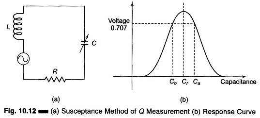
The points Ca, Cb and Cr are closer together when coil Q is high (sharp tuning) and far apart when Q is low (broad tuning). The value of Q can be then determined as follows.
Ca and Cb are the value of capacitances at the half power point and Cr is the value of the capacitance at resonance.
![]()
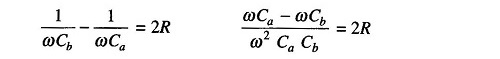
At half power points
![]()
Adding the two equations, we have
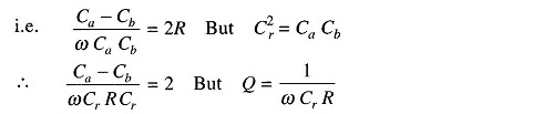
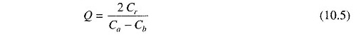
Therefore
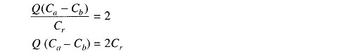
Therefore
In this method, the coil under rest is connected in series with a calibrated low loss capacitor. The frequency of the signal generator is kept at a suitable value and the output across the capacitor is measured by an electronic voltmeter. This method requires less expensive components than the Q meter.