Digital Capacitance Meter Block Diagram:
Digital Capacitance Meter – Since the capacitance is linearly proportional to the time constant, when a capacitor is charged by a constant current source and discharged through a fixed resistance, we can use a 555 timer along with some digital test equipment to measure capacitances.
One obvious way is to measure the time period of the oscillations. By choosing the right size of charging resistance, we can get a reading directly in microfarads or nanofarads. Unlike many capacitance measuring schemes, this one easily handles electrolytics up to the tens of thousands of microfarads.
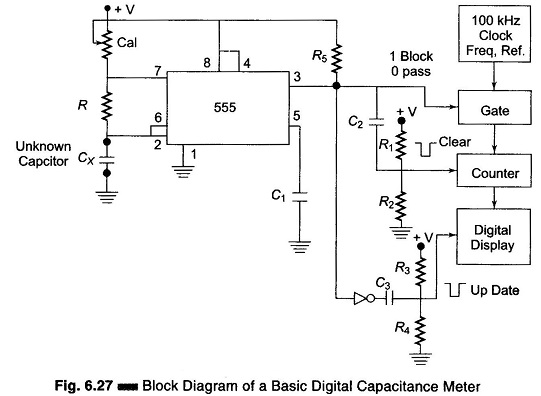
A better way is to measure only the capacitor discharge time, as shown in Digital Capacitance Meter Block Diagram Fig. 6.27. With this method, any leakage in the capacitor under test will make the capacitor appear smaller in value than it actually is, and is an effective indicator of how the test capacitor will behave in most timing and bypass circuits.
In this Digital Capacitance Meter Block Diagram circuit, the 555 timer is used as an astable multivibrator. At the peak of the charging curve, a digital counter is reset and a clock of 100 kHz pulses is turned on and routed to the counter. When the discharge portion of the cycle is completed, the display is updated and the value of the capacitor is readout. By selecting the proper reference frequency and charging currents, one can obtain a direct digital display of the value of the capacitance.
Be sure to properly shield the leads and keep them short for low capacity measurements, since the 50 Hz hum can cause some slight instability.