Digital Frequency Meter:
Principle of Operation of Digital Frequency Meter – The signal waveform is converted to trigger pulses and applied continuously to an AND gate, as shown in Fig. 6.4. A pulse of 1 s is applied to the other terminal, and the number of pulses counted during this period indicates the frequency.
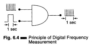
The signal whose frequency is to be measured is converted into a train of pulses, one pulse for each cycle of the signal. The number of pulses occurring in a definite interval of time is then counted by an electronic counter. Since each pulse represents the cycle of the unknown signal, the number of counts is a direct indication of the frequency of the signal (unknown). Since electronic counters have a high speed of operation, high frequency signals can be measured.
Basic Circuit of a Digital Frequency Meter:
The block diagram of a basic circuit of a digital frequency meter is shown in Fig. 6.5.
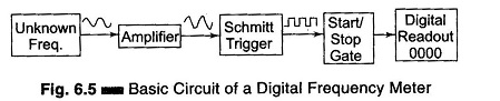
The signal may be amplified before being applied to the Schmitt trigger. The Schmitt trigger converts the input signal into a square wave with fast rise and fall times, which is then differentiated and clipped. As a result, the output from the Schmitt trigger is a train of pulses, one pulse for each cycle of the signal.
The output pulses from the Schmitt trigger are fed to a START/STOP gate. When this gate is enabled, the input pulses pass through this gate and are fed directly to the electronic counter, which counts the number of pulses.
When this gate is disabled, the counter stops counting the incoming pulses. The counter displays the number of pulses that have passed through it in the time interval between start and stop. If this interval is known, the unknown frequency can be measured.
Basic Circuit for Frequency Measurement:
The basic circuit for frequency measurement is as shown in Fig. 6.6. The output of the unknown frequency is applied to a Schmitt trigger, producing positive pulses at the output. These pulses are called the counter signals and are present at point A of the main gate. Positive pulses from the time base selector are present at point B of the START gate and at point B of the STOP gate.
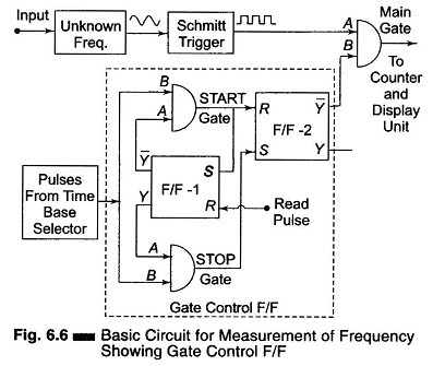
Initially the Flip-Flop (F/F-1) is at its logic 1 state. The resulting voltage from output Y is applied to point A of the STOP gate and enables this gate. The logic 0 stage at the output Y̅ of the F/F-1 is applied to the input A of the START gate and disables the gate.
As the STOP gate is enabled, the positive pulses from the time base pass through the STOP gate to the Set (S) input of the F/F-2 thereby setting F/F-2 to the 1 state and keeping it there.
The resulting 0 output level from Y̅ of F/F-2 is applied to terminal B of the main gate. Hence no pulses from the unknown frequency source can pass through the main gate.
In order to start the operation, a positive pulse is applied to (read input) reset input of F/F-1, thereby causing its state to change. Hence Y̅ = 1, Y = 0, and as a result the STOP gate is disabled and the START gate enabled. This same read pulse is simultaneously applied to the reset input of all decade counters, so that they are reset to 0 and the counting can start.
When the next pulse from the time base arrives, it is able to pass through the START gate to reset F/F-2, therefore, the F/F-2 output changes state from 0 to 1, hence Y̅ changes from 0 to 1. This resulting positive voltage from Y̅ called the gating signal, is applied to input B of the main gate thereby enabling the gate.
Now the pulses from the unknown frequency source pass through the main gate to the counter and the counter starts counting. This same pulse from the START gate is applied to the set input of F/F-1, changing its state from 0 to 1. This disables the START gate and enables the STOP gate. However, till the main gate is enabled, pulses from the unknown frequency continue to pass through the main gate to the counter.
The next pulse from the time base selector passes through the enabled STOP gate to the set input terminal of F/F-2, changing its output back to 1 and Y̅ = 0. Therefore the main gate is disabled, disconnecting the unknown frequency signal from the counter. The counter counts the number of pulses occurring between two successive pulses from the time base selector. If the time interval between this two successive pulses from the time base selector is 1 second, then the number of pulses counted within this interval is the frequency of the unknown frequency source, in Hertz.
The assembly consisting of two F/Fs and two gates is called a gate control F/F. The block diagram of a digital frequency meter is shown in Fig. 6.7.
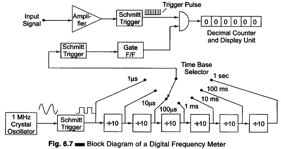
The input signal is amplified and converted to a square wave by a Schmitt trigger circuit. In this diagram, the square wave is differentiated and clipped to produce a train of pulses, each pulse separated by the period of the input signal. The time base selector output is obtained from an oscillator and is similarly converted into positive pulses.
The first pulse activates the gate control F/F. This gate control F/F provides an enable signal to the AND gate. The trigger pulses of the input signal are allowed to pass through the gate for a selected time period and counted. The second pulse from the decade frequency divider changes the state of the control F/F and removes the enable signal from the AND gate, thereby closing it. The decimal counter and display unit output corresponds to the number of input pulses received during a precise time interval; hence the counter display corresponds to the frequency.
High Frequency Measurement (Extending the Frequency Range):
The direct count range of digital frequency meter (DFM) extends from dc to a few 100 MHz. The limitations arises because of the counters used along with the DFM. The counters cannot count at the speed demanded by high frequency measurement.
This range of a few 100 MHz covers only a small portion of the frequency spectrum. Therefore, techniques other than direct counting have been used to extend the range of digital frequency meters to above 40 GHz. The input frequency is reduced before it is applied to a digital counter. This is done by special techniques. Some of the techniques used are as follows.
1. Prescaling
The high frequency signal by the use of high speed is divided by the integral numbers such as 2, 4, 6, 8 etc. divider circuits, to get it within the frequency range of DFM (for example synchronous counters).
2. Heterodyne Converter
The high frequency signal is reduced in frequency to a range within that of the meter, by using heterodyne techniques.
3. Transfer Oscillator
A harmonic or tunable LF continuous wave oscillator is zero beat (mixed to produce zero frequency) with the unknown high frequency signal. The LF oscillator frequency is measured and multiplied by an integer which is equal to the ratio of the two frequencies, in order to determine the value of the unknown HF.
4. Automatic Divider
The high frequency signal is reduced by some factor, such as 100:1, using automatically tuned circuits which generated an output frequency equal to 1/100th or 1/1000th of the input frequency.