DC Electric Field Strength Meter:
The DC Electric Field Strength Meter strength E can be measured by using (i) variable capacitor probe or generating voltmeter or (ii) a vibrating plate capacitor. These devices determine the electrical field intensity E by measuring either the induced charges or currents sensed by the electrodes.
(a) Variable Capacitor Field Meter
If a metallic electrode is kept in an electric field E, the total charge induced on its surface A is given by
If the area of the sensing electrode varies and the variation of the area of the sensing electrode is periodic, then the current flowing through the measuring electrode to the ground is
and hence the average value of electric field is
Hence the electric field is proportional to the current, I.
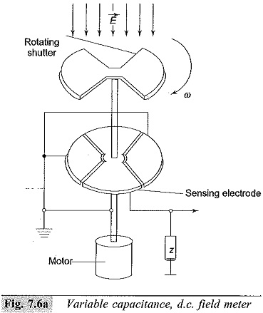
The arrangement of electrodes is shown in Fig. 7.6(a). The sensing electrode which is in the form of a circular disc is divided into sectors and shielded by a rotating shutter which rotates at an angular velocity ω. The shutter is driven at a constant speed by a motor. Two opposite sectors of the sensing electrodes are grounded and the other two are connected to ground through a measuring resistance R. The voltage across the resistance is measured and from this the electric field intensity E is determined. The induced current signal (voltage) is rectified by a phase sensitive detector operating with suitable phase angle relative to the movement of the shutter and is calibrated in terms of electric field E.
(b) Vibrating Plate Field Meter
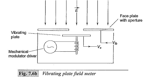
This meter consists of a fixed face plate with an aperture. A vibrating plate or electrode is located below the face plate and is made to oscillate at a fixed rate by a driver motor [Fig. 7.6 (b)]. Due to the vibrating motion of the driver plate a variable voltage V between the two plates, i.e. the face plate and the vibrating plate is generated.
This is essentially a variable capacitor and the electric field E is proportional to the voltage generated V. The instrument is calibrated by placing it in a known electric field.


