Transistor Clipper Circuit and Waveforms:
Transistor Clipper Circuit – The transistor has two pronounced nonlinearities—one occurs when the transistor passes from cutin region to the active region and the second occurs when it passes from active region to the saturation region. If any input signal makes excursion which takes the transistor across the boundary between cutin region and active region, or across the boundary between the active region and saturation region, a portion of the input signal waveform will be clipped off.
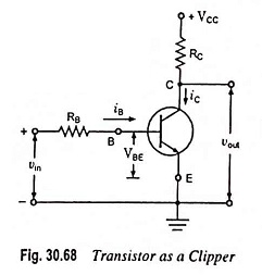
Portion of the input waveform which keeps the transistor in the active region shall appear at the output without any distortion. In such a case, it is the input current rather than the input voltage that should have the waveform of the signal of interest. Obvious reason is that over a large signal excursion in the active region, the transistor output current responds linearly to the input current but is related quite nonlinearly to the input voltage. Therefore, a current drive is used in a Transistor Clipper Circuit, as illustrated in Fig. 30.68. The resistor RB must be large compared to the input resistance of the transistor in the active region. The input base current then has the waveform of input voltage and
![]()
Waveforms for the transistor clipper for ramp input are shown in Fig. 30.69.
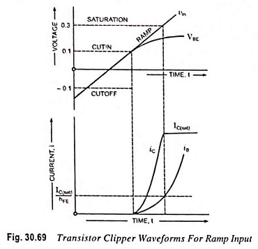
The voltages are taken for a germanium transistor. At -0.1 V, the transistor is in the cutoff region. At 0.1 V, it starts conducting and goes into the active region. At 0.3 V, the transistor goes into the saturation region and voltage VBE is limited to 0.3 V. The input base current iB increases as the transistor passes from cutoff region to active region and eventually into saturation.
In the active region, the output current (collector current iC) will be of the same form as the input base current. In saturation region, however, collector current will become constant and becomes IC(sat).
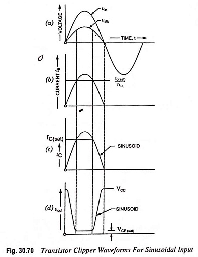
Waveforms for the transistor clipper for sinusoidal input are shown in Fig. 30.70.