Transistor Testing Circuit:
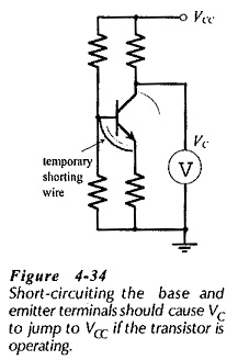
In-Circuit Testing – A quick test to check if a transistor is operational can be performed while the device is still connected in a circuit. Consider Fig. 4-34, which shows a voltmeter connected to measure the transistor collector voltage (VC). The VC measurement is noted, then the base and emitter terminals are temporarily short-circuited, as illustrated. This should turn the transistor off, and VC should Jump to approximately the circuit supply voltage (VCC). When the shorting wire is removed, VC should return to its previous level. If the change in the VC level does not occur, the Transistor Testing Circuit is not operational. This may be due to a faulty transistor, or to some other problem in the circuit.
Ohmmeter Tests:
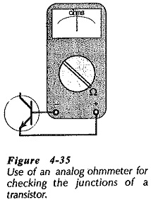
An ohmmeter may be used for checking the transistor emitter-base and collector-base junctions. As in the case of a diode, the measured resistance of a forward-biased junction depends upon the ohmmeter range. With an analog ohmmeter, a good forward-biased pit-junction typically indicates half-scale, (see Fig. 4-35). A good reverse-biased junction gives a very high resistance measurement. The terminal polarity of some multimeters is reversed when used as an ohmmeter. This should be checked with a voltmeter. The measured resistance between the collector and emitter terminals of a good Transistor Testing Circuit should be very high regardless of the ohmmeter terminal polarity.
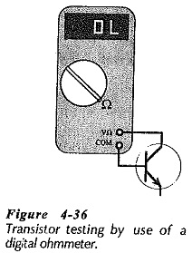
A digital ohmmeter may show a resistance of a few megohms when measuring a good forward-biased junction, and an open-circuit indication (OL) for a reverse-biased junction, (Fig. 4-36). It should also indicate open-circuit when measuring between the collector and emitter terminals. The diode testing terminals on a digital multimeter may also be used for testing translator CB and EB junctions. Some digital multifunction instruments have testing facilities for measuring transistor hFE values.
Characteristic Plotting:
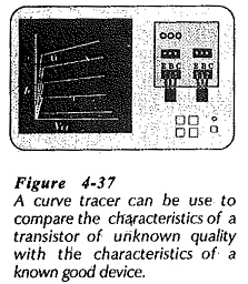
A Transistor Testing Circuit may be rapidly checked by use of a curve tracer, (see Fig. 4-37). Two transistor sockets are normally provided to display the characteristics of two devices. A switch permits selection of either socket. The characteristics of a known good transistor should first be displayed. Then, the switch should be operated to display the characteristics of the Transistor Testing Circuit under investigation.
Transistor Testing Circuit characteristics may be plotted by obtaining a table of corresponding levels of current and voltage, as already discussed. A more convenient method of plotting characteristics using an XY recorder is illustrated in Fig. 4-38. One power supply is connected to produce base current (IB) via resistor R1, and the other provides IC flow through R2. The collector and emitter terminals are connected to the horizontal input terminals of the XY recorder, and the voltage drop across resistor R2 provides the vertical input. The base current is set at a several convenient levels, and (at each IB level) VCC is slowly increased from zero to cause the pen to trace one line of the transistor output characteristics
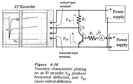
A convenient selection for the horizontal and vertical scales of the XY recorder is 1 V/cm. If R2 = 1 kΩ, each 1 V drop across R2 represents 1 mA of collector current. So, the IC (vertical) scale on the characteristics is 1 mA/cm, and the VCE scale is 1 V/cm.