Transformer Testing Methods:
Two chief difficulties which do not warrant the Transformer Testing Methods by direct load test are:
- Large amount of energy has to be wasted in such a test,
- It is a stupendous (impossible for large transformers) task to arrange a load large enough for direct loading.
Thus performance characteristics of a transformer must be computed from a knowledge of its equivalent circuit parameters which, in turns, are determined by conducting simple tests involving very little power consumption, called nonloading tests. In these tests the power consumption is simply that which is needed to supply the losses incurred. The two nonloading tests are the open-circuit (OC) test and short-circuit (SC) test.
In both these tests voltage, current and power are measured, from which the resistance and reactance of the input impedance can be found, as seen in each test. Thus only four parameters can be determined which correspond to the approximate equivalent circuit of transformer of Fig. 3.16(b).
Before proceeding to describe OC and SC tests, a simple test will be advanced for determining similar polarity ends on the two windings of a transformer.
Polarity Test of Transformer:
Similar polarity ends of the two windings of a transformer are those ends that acquire simultaneously positive or negative polarity of emf’s induced in them. These are indicated by the dot convention as illustrated already. Usually the ends of the LV winding are labelled with a small letter of the alphabet and are suffixed 1 and 2, while the HV winding ends are labelled by the corresponding capital letter and are suffixed 1 and 2 as shown in Fig. 3.19. The ends suffixed 2 (a2, A2) have the same polarity and so have the ends labelled 1 (a1, A1).
In determining the relative polarity of the two-windings of a transformer the two windings are connected in series across a voltmeter, while one of the windings is excited from a suitable voltage source as shown in Fig. 3.19. If the polarities of the windings are as marked on the diagram, the voltmeter should read V = V1 ~ V2. If it reads ( V1 + V2), the polarity markings of one of the windings must be interchanged.
The above method of polarity Transformer Testing Methods may not be convenient in field testing of a transformer. Alternatively the polarity Transformer Testing Methods can be easily carried out by a dc battery, switch and dc voltmeter (permanent magnet type which can determine the polarity of a voltage) as shown in the simple setup of Fig.3.19(b). As the switch on the primary side is closed, the primary current increases and so do the flux linkages of both the windings, inducing emfs in them.
The positive polarity of this induced emf in the primary at the end to which the battery is connected (as per Lenz’s law). The end of secondary which (simultaneously) acquires positive polarity (as determined by the dc voltmeter) is the similar polarity end. The reverse happens when the switch is opened, i.e. the similar polarity end of the secondary is that end which acquires negative potential.

Open Circuit Test of Transformer or No Load Test of Transformer:
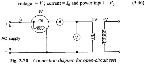
The purpose of this test is to determine the shunt branch parameters of the equivalent circuit of transformer (Fig. 3.14(c)). One of the windings is connected to supply at rated voltage, while the other winding is kept open-circuited. From the point of view of convenience and availability of supply the test is usually performed from the LV side, while the HV side is kept open circuited as shown in Fig. 3.20. If the transformer is to be used at voltage other than rated, the test should be carried out at that voltage. Metering is arranged to read.
Equivalent Circuit of Transformer:
Figure 3.21(a) shows the equivalent circuit as seen on open-circuit and its approximate version in Fig. 3.21(b). Indeed the no-load current I0 is so small (it is usually 2-6% of the rated current) and R1 and X1 are also small, that V1 can be regarded as = E1 by neglecting the series impedance. This means that for all practical purposes the power input on no-load equals the core (iron) loss i.e.,
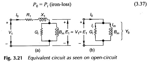
The shunt branch parameters can easily be determined from the three readings (Eq. (3.36)) by the following circuit computations and with reference to the no-load phasor diagram of Fig. 3.4.
![]()
It then follows that
![]()
These values are referred to the side (usually LV) from which the test is conducted and could easily be referred to the other side if so desired by the square of transformation ratio. The transformation ratio if not known can be determined by connecting a voltmeter on the HV side as well in the no-load test.
It is, therefore, seen that the OC test yields the values of core-loss and parameters of the shunt branch of the equivalent circuit.
Short Circuit Test of Transformer:
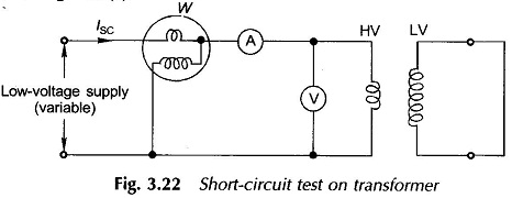
This test serves the purpose of determining the series parameters of a transformer. For convenience of supply arrangement and voltage and current to be handled, the test is usually conducted from the HV side of the transformer, while the LV is short-circuited as shown in Fig. 3.22.
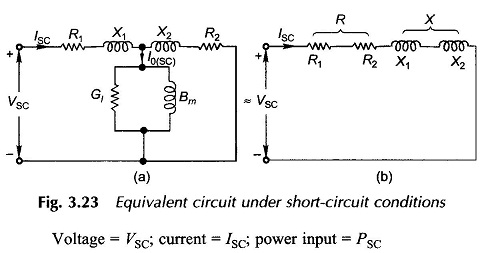
The equivalent circuit of transformer as seen from the HV under short-circuit conditions is drawn in Fig. 3.23(a). Since the transformer resistances and leakage reactances are very small, the voltage VSC needed to circulate the full-load current under short-circuit is as low as 5-8% of the rated voltage. As a result the exciting current I0(SC) under these conditions is only about 0.1 to 0.5% of the full-load current (I0 at the rated voltage is 2-6% of the full-load current). Thus the shunt branch of the equivalent circuit can be altogether neglected giving the equivalent circuit of Fig. 3.23(b).
While conducting the SC test, the supply voltage is gradually raised from zero till the transformer draws full-load current. The meter readings under these conditions are:
 Since the transformer is excited at very low voltage, the iron-loss is negligible (that is why shunt branch is left out), the power input corresponds only to the copper-loss, i.e.
![]()
From the equivalent circuit for Fig. 3.23(b), the circuit parameters are computed as below:
![]()
These values are referred to the side (HV) from which the test is conducted. If desired, the values could be easily referred to the other side.
It is to be observed that the SC test has given us the equivalent resistance and reactance of the transformer, it has not yielded any information for separating these into respective primary and secondary values.
It was observed that OC and SC tests together give the parameters of the approximate equivalent circuit of Fig. 3.16(b) which as already pointed out is quite accurate for all important computations.