Indirect Testing of Circuit Breaker:
With the increase in the breaking capacity of the HV circuit breakers, it has become uneconomical and unpracticable to increase the short-circuit capacity of testing station. It is consequently necessary to utilize some form of Indirect Testing of Circuit Breaker.
The important methods of Indirect Testing of Circuit Breaker are:
- Unit Testing of Circuit Breaker.
- Synthetic Testing of Circuit Breakers.
Unit Testing of Circuit Breaker:
It is a common practice to design breakers with a number of rupturing units in series, each having a capacity within the available testing power. A test on one unit can be accepted as proof for all units. Such tests are known as Unit tests. Up to short-circuit levels of some 35,000 MVA this method has proved satisfactory as this design limitation has not seriously affected the cost of the circuit breakers, but recently the rupturing capacities of the modern circuit breakers have exceeded this limit and is of the order of 50,000 MVA which calls for units of higher rupturing capacities for greater economy.
Synthetic Testing of Circuit Breakers:
Synthetic testing is a practical and economical solution for the testing of circuit breakers of high rupturing capacities, without actually employing the corresponding short-circuit capacity of the testing station. Although there is much to indicate that synthetic test could be made to give conditions as severe as those of the direct test, there is little evidence of a conclusive nature to show in any general way the steps necessary to predetermine its relative severity.
The synthetic circuit is designed to simulate as accurately as possible the electrical stresses impressed on the circuit breaker during the interruption of a fault current under system conditions.
Principle of Synthetic Testing of Circuit Breaker:
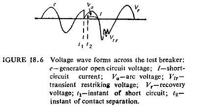
When switch S in Fig. (18.5) is closed short-circuit current I flows through the breaker B and when the test breaker B begins to open an arcing voltage Va appears across the breaker terminals as shown in Fig. (18.6). At current zero when the arc is extinguished a transient voltage Vtr appears across the breaker whose form is determined by the geperator characteristics and the circuit constants L.
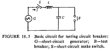
The breaker has to withstand this transient recovery voltage if it is to clear the circuit.
It is seen that during the period of main current flow there is comparatively small arcing voltage across the breaker and that during the period of transient recovery voltage little or no current flows through the breaker. It can be inferred that for testing the breakers rupturing ability there is no need to use a single high power source. Instead the current can be supplied by a comparatively low voltage source, since the arc voltage is usually very small of the order of 1/20th of the rated voltage of the breaker, and the voltage can be applied from a low energy HV source at the point of current zero to simulate recovery voltage.
By this method, it is therefore possible to obtain an effective gain in testing power. This is generally referred to as the magnification factor or the multiplication factor which is approximately equal to the ratio of the test recovery voltage to the voltage of the current source.
Synthetic testing therefore attempts to secure artificially a large rupturing power by superimposing on a normal frequency test current from a conventional generator, a very high voltage of an impulse wave at the time of break. In effect only a voltage source is required in addition to the existing plant equipment making the cost a fraction of the additional generator plant to give similar increase in power. The capacity of the existing short-circuit testing stations can in this way be increased many times.
Types of Synthetic Testing Circuit Breaker:
The synthetic testing circuits can be of two types:
- Current Injection Method,
- Voltage Injection Method.
During the current interruption process, there is a period though small (1-25 μ sec) when arcing occurs. This is termed as energy balance period in the arc column in the proximity of current zero. The recovery voltage will therefore get switched on either before or after current zero. Depending on whether Vr is switched on before or after current zero the type of synthetic testing is known as current injection or voltage injection respectively.
Synthetic Testing Circuits: A description of various circuits of synthetic testing, their advantages and disadvantages are given below.
(a) Current Injection Method:
This again is of two types: (i) parallel current injection and (ii) series current injection. The two methods are different only in the manner in which the voltage circuit is closed on to the test breaker. In the first method the voltage circuit is inserted in parallel with the test breaker, while in the second method it is inserted in series. The first method is popular in Germany and is known as WeilDobke circuit and the second method was suggested by Koplan Bashatyr (U.S.S.R.) and is known as Russian circuit.
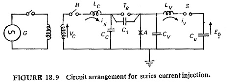
Parallel Current Injection Method (Weil Dobke Test Circuit): The essential features of Weil-Dobke circuit are illustrated in Fig. (18.7). The accurate simulation of the stresses on the switch are achieved by connecting the HV circuit to it, a comparatively long time before the short-circuit current zero when exact timing is less critical. With suitable HV Oscillating circuits this superposition of currents without any extraneous control produces the required stresses on the breaker.
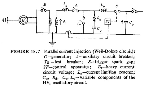
Initially generator G is excited and Lg set to give the required test current, make switch M open and the auxiliary breaker A and test breaker TB are closed.
In the voltage circuit capacitor Cu is charged to give the required recovery voltage and the spark gap S is set ready to be fired. Lv is so chosen that when iv flows consequent to the triggering of the gap, the rate of change of current through zero is the same as that of the test current. Cv is chosen to give the required transient restriking voltage frequency.
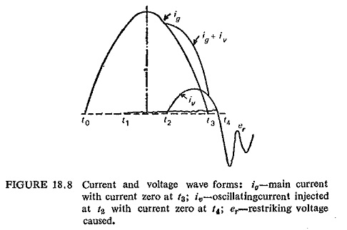
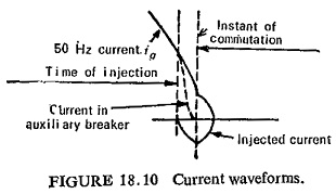
At time t0, the make switch M is closed and the normal frequency 50 Hz current ig flows in the circuit breaker. At time T1 the auxiliary breaker A and test breaker TB begin to open so that they are fully open at the following current zero (t3) (Fig. (18.8)). At time t2 the spark gap S is fired and the current iv flows in the test breaker. The frequency of this current is determined by Lv and Cv and timed so that its peak approximately coincides with zero of current ig. At time t3 when the current ig becomes zero it is interrupted by the auxiliary breaker A and the Indirect Testing of Circuit Breaker carries current iv from the voltage circuit. When this current becomes zero at t4 the restriking voltage transient er appears across the breaker. The magnitude and frequency of this er depend on the voltage to which the capacitor Cu is charged and the parameters Cv and Lv. This enables the supply of current and voltage at the moment of zero current from one and the same source.
In this way breaking capacities up to ten or more times the short-circuit capacity of the short-circuit generator can be achieved and the Indirect Testing of Circuit Breaker can be subjected to exactly the same stresses as in an actual system.
Series Current Injection Method (U.S.S.R. circuit): It differs from the Weil-Dobke circuit in the way in which the small loop of current from the voltage source is introduced.
The voltage circuit is connected across the auxiliary breaker, instead of the Indirect Testing of Circuit Breaker and the source capacitance. Cu is charged to the opposite polarity, with the result that the injected current flows in the opposite direction to the 50 Hz current, and thus subtracts from it (Fig. (18.10)). As the current and voltage circuits are series connected, it is rather difficult to select circuit parameters to suit both the current and voltage circuits which would at the same time give required restriking voltage transient. The arrangement is particularly well suited for low frequency circuits.
(b) Voltage Injection Method:
In this Voltage Injection Method employed by Siemens, Germany, the voltage circuit is closed on to the test breaker after current zero. It advantageously uses the high current circuit to supply part of the transient voltage impressed on the test piece. By selecting voltage natural frequency suitably and damping the high current circuit has a transient recovery voltage with a definite characteristic which is required for the initial phase of the transient recovery voltage. The high voltage source is to be switched into action approximately at the time of the first peak of the recovery voltage of the high current source, so that the required voltage stresses are continued without any zero pause.
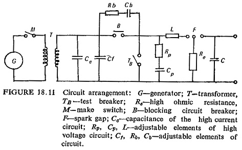
Figure (18.11) shows the circuit in a simplified form. High current circuit is fed from the short-circuit generator through a make switch, which is initially open to the transformer T. On the high voltage side are the blocking circuit breaker and the Indirect Testing of Circuit Breaker. The circuit is closed through the closing switch (at about the crest value of the driving voltage) and about the same time the blocking circuit breaker and the test breaker receive either simultaneously or nearly at the same time tripping impulses and interrupt the short-circuit current shortly thereafter. This is followed
by the oscillatory transient recovery voltage appearing at the terminals of the transformer with essentially a single frequency. Capacitances are connected in parallel with the blocking and test breakers which transmit the transient recovery voltage of the high current source to the breaker on test and enable the delivery of necessary energy for the arc gap in case a post-arc current occurs. These capacitances are so distributed that the test breaker is subjected to the maximum applied voltage. The charged condenser of the high voltage circuit can be switched in with practically no time delay by means of a triggering gap in conjunction with a switching gap.
Compound Circuit: A compound circuit has been installed by the International General Electric, Philadelphia, U.S.A. for proving and development testing of circuit breaker modules and circuit breakers up to 50,000 equivalent three-phase module MVA. The compound circuit in theory is similar to the Weil-Dobke synthetic circuit with some additions to the WeilDobke circuit. The purpose of the compound circuit facility is to create laboratory conditions equivalent to those in the field by matching high short-circuit current from the test generators with high voltage recovery voltage from energy storage capacitors. The synchronization of recovery voltage to final current zero is accomplished with great precision by connecting the voltage source into the circuit about 8000µ sec before current zero and disconnecting the current source about 400µ sec before current zero so that when current zero does occur synchronization is the same as if the current had come from the high voltage source throughout the test.
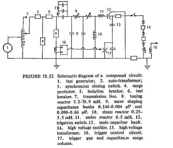
A simplified schematic diagram of the compound circuit is shown in Fig. (18.12).
Validity of Synthetic Tests: Because the synthetic circuit is not identical with that of direct, differences may be reflected in circuit breaker performances. From a knowledge of the process involved in arc rupture, it is possible to assess the significance of dissimilarities. There are circuit breakers (e.g. air-break, arc-chute type) where the arc voltage is high in relation to the circuit voltage, and any reduction in the latter may result in an appreciable departure from the normal current form. On the other hand other types of circuit breakers for instance axial air-blast circuit breakers which can have low arcing voltage characteristics, are well suited to the synthetic test. It would seem highly desirable in an investigation in which it is intended to develop synthetic testing to a stage where it can be used as a supplement or an alternative to the direct testing.
However, following are some of the conclusions of various synthetic testing techniques.
- Basic principle of synthetic test using parallel current injection is sound.
- In all cases where the synthetic test circuit has been set up with particular attention given to the values and forms of the voltages and currents around the current zero period, no significant difference in severity has been found between the direct and synthetic tests conducted on air-blast circuit breakers over a range of 33-1200 MVA.
- Validity of parallel current injection of synthetic testing will hold for powers beyond 1200 MVA.
- The frequency of the injected current is not unduly critical over the 350-1000 Hz range. This range over which validity of synthetic test has been shown to hold is adequate for most practical purposes.
- The time of injection of current loop is important but if injection is such that the peak of injected current loop lies within ±100μ sec of the 50 Hz current zero, severity will remain unaltered. No difficulty as been experienced in maintaining injection timing well within these limits.