General Methods of Testing Protective Gear:
The General Methods of Testing Protective Gear are namely,
- Primary Injection,
- Secondary Injection,
- Measurement of Time,
Primary Injection:
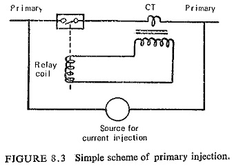
These tests are limited by the manner in which current can be passed through the primary winding of the current transformers of the protective gear under test. Generally it is possible to obtain access to the primary connections to enable current at low voltage to be injected, but in certain cases, such as when CTs are fitted in the bushings of power transformers, other means of injection have to be used. Primarily these tests are performed for checking the polarity and correctness of the primary and secondary wiring. When carrying out this test the entire circuit comprising CT secondaries, relay coils, trip and alarm circuits, and all intervening wiring is checked. Figure (8.3) shows a simple scheme of primary injection.
The heavy test current required for injection is either obtained by running a generator on short circuit or by means of a portable injection transformer arranged to operate from the local mains supply and having several low voltage heavy current windings. The secondary low voltage windings can be connected in series or parallel depending on the current required and resistance of the primary circuit. The output can be controlled by a tapped reactor or an auto-transformer.
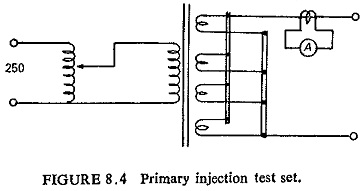
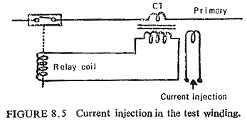
A typical primary-injection transformer is shown in Fig. (8.4), which is usually of about 10 KVA rating with a ratio of 250/10+10+10+10 volts. A current up to 1000 A can be obtained by connecting all the four secondary windings in parallel. If the main CTs are fitted with test windings these can be used for primary injection instead of the primary winding (Fig. (8.5)). The current required for primary injection is then greatly reduced, but these test windings are not always provided because of space limitations in the main CT housings.
Secondary Injection:
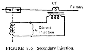
In this case the testing current is injected into the secondary circuits of the protective gear as shown in Fig. (8.6).
Advantages:
One of the advantages of these tests is that fault conditions are simulated with relatively small currents and the amount of power consumed by such tests is small.
Disadvantages:
A limitation of testing by this means is that the ratio and phase-angle errors of the instrument transformers and the phasing of their secondary connections are not taken into account.
Measurement of Time:
It is often necessary to make measurements of time to determine the speed of fault clearance and the factor of safety available for discrimination. Timing devices for protective equipment’s operating in not less than 0.1s are well known, and normally comprise a cycle counter, Warren clock or stop-watch controlled either manually or electrically. On account of the errors introduced in starting and stopping most of these devices are not sufficiently accurate for checking the time of operation when this is less than 0. 1s. Special apparatus has to be used which can measure time duration of the order of a few milliseconds with fair accuracy. The requirements of such apparatus are accuracy, direct reading, robustness and portability.
The apparatus is, however, necessary in making detailed investigations into the causes of maloperation of high speed protective equipment, particularly when their functioning depends upon the sequential operation of a number of relays.