Grounding of Impulse Testing Laboratories:
An earth or ground system means an established stable .reference potential normally taken to be zero. There are three types of Grounding of Impulse Testing Laboratories are:
-
the ideal ground,
-
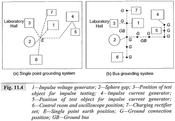
single point ground (Fig. 11.4a), and
-
the bus ground (Fig. 11.4b).
Of all these, the best ground is the ideal ground which cannot be realized in practice. The next preferred ground is the single point ground, and the bus ground is least satisfactory. Ideal ground can be approximated by an equipotential plane realized by a finite conducting material. The laboratory is covered by a sheet of copper metal welded into a single unit. But this is very costly and is used rarely. A single point ground is commonly used. In this (see Fig. 11.4a) an earthing grid is installed within the laboratory floor, the connection from the grid is given by a large sized copper conductor to a point identified as a common ground point. The Grounding of Impulse Testing Laboratories connections of various equipments and other components of the high voltage test circuit are made to the common ground.
High voltage impulse tests give rise to high currents of several kiloamperes, and the rate at which the currents may change ranges between 107 to 109 A/s. If proper care is not taken, flashover or damage to control gear and risk of life to persons can occur. In order to avoid these difficulties, copper strips are used instead of round conductors to minimize the inductance in the Grounding of Impulse Testing Laboratories circuit. Secondly, metal grid embedded in a concrete floor gives rise to less resistance and inductance in the ground circuit. The ground is effective only when large size strips are used with close spacing. The ground system should ensure the following conditions:
- imperfections of grounding system are to be avoided, as they cause excessive voltage difference between points and cause flashovers, damage, or danger to human life,
- the imperfections will cause excessive loop currents along the sheaths of measuring cables, which will introduce errors in measurements,
- the grounding system should be such that the voltage drop along the ground system, the voltage at a loop, and the circulating currents in the loops are avoided.
- metal conduits should be used for the measuring and control cables to avoid neutral inductance effect between the ground grid and the cables.
A typical good earthing system consists of a copper network with meshes of 1 m width laid down below the ground level around the impulse test area and well connected. This network is extended over the entire area comprising all equipment such as testing transformers, charging h.v. rectifier set, test bay, etc. The grid should be electrically connected to all the metallic frames and reinforcing iron in the concrete walls and pillars of the building at their bottom points. Impulse test area must be provided with a spread, stretched, or expanded copper grid on the floor of thickness of about 2 mm with Grounding of Impulse Testing Laboratories rods driven into the earth to a depth equal to the height of the impulse generator. The rods are welded to the inside copper grid as well as surface copper grid. Earth connection facility is to be provided for every 16 sq. m area so that the shortest lead can be used from any position inside the laboratory.
Where ionization measurements are to be made, the earthing system should keep the RIV level from external sources to the lowest value. In addition, the high frequency energy produced during impulse tests should not cause any trouble around the test area. If this is to be met the entire laboratory should be built into a Faraday cage.
Electromagnetic Shielding and Earth Return in High Voltage Laboratories:
A high voltage laboratory, small, medium or large in size should have some type of screening against electrostatic and electromagnetic field interference. The screening is essential if partial discharge measurements are to be made in the laboratory. An attenuation of less than 40 db is needed for attenuation of electrical signals in the frequency range of 1 MHz, while a still lower attenuation is needed for electromagnetic signals. In larger test laboratories attenuation levels due to interference are higher and arise mostly due to imperfect screening. One way to check the screening is to tune a portable pocket-radio and walk around the laboratory tuning the radio to different frequencies between 500 kHz to 10 MHz. The signal should not be heard. However, it is often found that the signal level increases significantly when a cable or an electrical outlet is crossed. If it is possible, the same check may be carried out with the automatic volume control (gain control) disconnected. The sources of disturbance inside the laboratories are
- switching transients due to switching-on or switching-off of loads like lifts or cranes, transformers, etc.,
- rectifier circuits, and
- shielded cables acting as antennas for outside signals.
Care should be taken to see that the above are avoided. The best screening is obtained if the roof, the walls and the flooring area are screened with an expanded metal wire mesh and joined together. Further, all electric conductors are fully screened in metal conduits which are run below the floor metal network.
For the purpose of measurement, one point in the test circuit such as the base of a test object or an impulse voltage generator should be made a reference Grounding of Impulse Testing Laboratories or a zero potential point. This is usually disturbed in measurements for fault indication in transformers during impulse testing, tests with chopped waves etc. as spikes are introduced into the test circuits due to low-voltage conductors that run into the control room from the impulse test area which carry the operating signals of large magnitude to control impulse generator, sphere gaps, etc. As such a potential difference is created momentarily during the transient period between the base of impulse voltage generator and that of the base of the measuring voltage divider and test object. These differences are carried on to the measuring device which will give erroneous results. These voltage differences can he reduced by reducing the impedance of the Grounding of Impulse Testing Laboratories side of the test circuit. The most effective method for reducing the voltage differences is to have the return conductor in the form of a metal sheet placed on the top of the floor. Some laboratories used coarse copper nets or aluminium nets or aluminium sheets, but they are not very effective.
The high voltage laboratory must be earthed to
- protect the equipment against the lightning strokes, and
- to protect the equipment from short circuits inside the laboratory from the power supply source.
If not properly earthed, these will give rise to potentials which are different at different points in the laboratory thus causing unnecessary danger to human life and damage to the equipment.
The acoustical attenuation of the building is also important. It is necessary in large laboratories to have comfortable and clear communication between persons at different locations inside the laboratory. Reverberation inside the laboratory should be avoided. To get the desired effect, the laboratory should have perforated holes and fibreglass or some such material fixed to the walls. The above aspects need careful consideration in the design of a high voltage laboratory.