Resistance Grounding:
In order to limit the magnitude of earth fault current, it is a common practice to connect the neutral point of a 3-phase system to earth through a resistor. This is called Resistance Grounding.
When the neutral point of a 3-phase system (e.g. 3-phase generator, 3-phase transformer etc.) is connected to earth (i.e. soil) through a resistor, it is called Resistance Grounding.
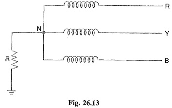
Fig. 26.13 shows the grounding of neutral point through a resistor R. The value of R should neither be very low nor very high. If the value of earthing resistance R is very low, the earth fault current will be large and the system becomes similar to the solid grounding system. On the other hand, if the earthing resistance R is very high, the system conditions become similar to ungrounded neutral system. The value of R is so chosen such that the earth fault current is limited to safe value but still sufficient to permit the operation of earth fault protection system. In practice, that value of R is selected that limits the earth fault current to 2 times the normal full load current of the earthed generator or transformer.
The following are the advantages of Resistance Earthing:
1. By adjusting the value of R, the arcing grounds can be minimized. Suppose earth fault occurs in phase B as shown in Fig. 26.14. The capacitive currents IR and IY flow in the healthy phases R and Y respectively. The fault current IF lags behind the phase voltage of the faulted phase by a certain angle depending upon the earthing resistance R and the reactance of the system upto the point of fault. The fault current IF can be resolved into two components viz.
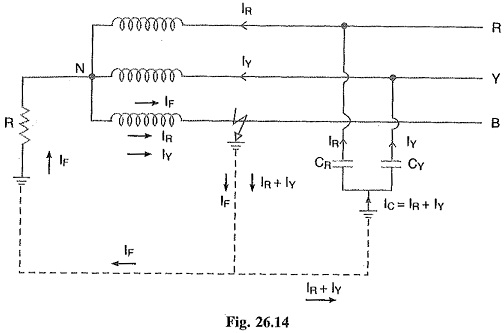
(a) IF1 in phase with the faulty phase voltage.
(a) IF2 lagging behind the faulty phase voltage by 90°.
The lagging component IF2 is in phase opposition to the total capacitive current IC. If the value of earthing resistance R is so adjusted that IF2 = IC, the arcing ground is completely eliminated and the operation of the system becomes that of solidly grounded system. However, if R is so adjusted that IF2 < IC, the operation of the system becomes that of ungrounded neutral system.
2. The earth fault current is small due to the presence of earthing resistance. Therefore, interference with communication circuits is reduced.
3. It improves the stability of the system.
The following are the disadvantages of resistance grounding :
1. Since the system neutral is displaced during earth faults, the equipment has to be insulated for higher voltages.
2. This system is costlier than the solidly grounded system.
3. A large amount of energy is produced in the earthing resistance during earth faults. Sometimes it becomes difficult to dissipate this energy to atmosphere.
Applications:
It is used on a system operating at voltages between 2.2 kV and 33 kV with power source capacity more than 5000 kVA.
Reactance Grounding:
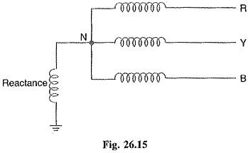
In this Reactance Grounding system, a reactance is inserted between the neutral and ground as shown in Fig. 26.15. The purpose of reactance is to limit the earth fault current By changing the earthing reactance, the earth fault current can to changed to obtain the conditions similar to that of solid grounding.
This method is not used these days because of the following disadvantages:
- In this system, the fault current required to operate the protective device is higher than that of resistance grounding for the same fault conditions.
- High transient voltages appear under fault conditions.