Armature Resistance Control Method of DC Motor:
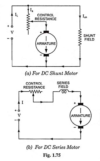
In this armature resistance control method of speed control, reduced speeds are obtained by inserting resistance in the armature circuit. It may be employed with series, shunt and compound wound motors. For the last two types, the series resistance is connected between the shunt field and armature, not between the line and motor.
In case of a dc shunt motor an increase in armature circuit resistance will cause more voltage drop in the armature circuit, so the speed will be reduced. Field current will remain unaffected, as the shunt field is directly connected across the supply voltage.
For a constant torque load, the armature current remains the same so input to the motor remains the same but the output decreases in proportion to the speeds. Operating costs are, therefore, comparatively high for long time running at reduced speed. In case of fans and centrifugal pumps where the load torque decreases with the decrease in speed, the losses are considerably low and because of its low initial cost and simplicity this method may be quite convenient and economical for short-time or intermittent slowdowns. Wide range of speed (below normal one) can be obtained by this method and at the same time motor will develop any desired torque over its operating range.
The main advantage of this armature resistance control method is that speeds below base speed down to creeping speeds of only a few rpm are easily available. This method of speed control, therefore, is employed where speeds lower than rated one are required for a short period only and also occasionally as in printing machines, cranes and hoists where the motor is frequently started and stopped. This method of speed control is also employed where the load drops off rapidly with the decrease in speed, as in fans and blowers.
In case of a dc series motor an increase in armature circuit resistance will cause more voltage drop in the armature circuit, so speed will be reduced. The torque which is proportional to the product of the flux and armature current will also be reduced with the increase in armature circuit resistance as increase in armature circuit resistance will reduce the armature current and the flux which also depends upon the armature current. In order to obtain different speeds for constant load torque, the armature current is kept constant so the flux. The resistance in the armature circuit is increased to reduce the speed.
The drawbacks of armature resistance control method for machines with shunt fields are not as important in the speed control of dc series motors.
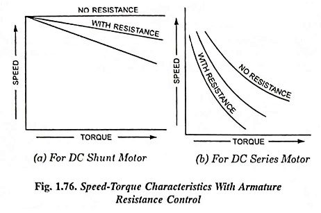
The poor speed regulation that is inherent in this method has no significance for the control of dc series motors, since the speed characteristic of a dc series motor is a rapidly drooping curve. The power loss in the control resistance for many applications of dc series motors is not too serious, since in these applications the control is utilized for a large portion of time for reducing the speed under light-load conditions and is only employed intermittently when the motor is carrying full load. The speed-torque characteristics of dc series motors with resistance control are shown in Fig. 1.76 (b). The maximum range of speed control of about 3 : 1 will be available depending on the load. This method of speed control is most economical for constant torque drives. This method of speed control is employed chiefly for dc series motors driving cranes, hoists, trains etc. because such drives operate on intermittent duty.
The speed-torque characteristics of armature resistance control method as applied to dc shunt and series motors are shown in Figs. 1.76 (a) and 1.76 (b) respectively.