Reversible Drive using Armature Current Reversal:
A schematic of a reversible drive using contactors to reverse the Armature Current Reversal for reversing the rotation is shown kin Fig. 4.81. The contactors F1 and F2 are provided for rotation in the forward direction, whereas R1 and R2 in the reverse direction. This arrangement reverses the current in the armature retaining the direction of current in the bridge thyristors. During speed reversal, the load on the motor is removed. The following stages are involved in the reversal of the motor.
Stage 1: The motor is in the steady state in the forward direction. During this stage F1 and F2 are in the closed position. The Armature Current Reversal flows in the armature from A to B. At the instant of providing the signal to reverse, the motor is unloaded. A small no-load current flows through the motor.
Stage 2: The speed reversal takes place in this stage. The contactors must be operated at zero current, for a longer life. The firing angle is retarded such that the applied voltage is less than the induced voltage. This makes the armature current zero. The contactors F1 and F2 are opened using a zero current detector. The switches R1 and R2 are closed. Opening and closing of switches introduce a kind of time lag. During this time the Armature Current Reversal of the motor is not energised and the motor starts coasting. Speed may be assumed to be constant due to large inertia.
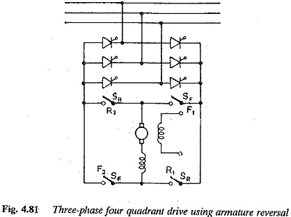
After closing the switches R1 and R2 the firing angle is advanced so that induced voltage. The motor comes to rest. The firing angle is adjusted such that the retardation takes place at constant current. The motor operates as a regenerative brake during this time. All the kinetic energy is returned to the mains by the time the motor approaches zero speed.
The firing angle is further advanced, the converter operates as a rectifier and the machine accelerates in the reverse direction. The motor attains rated speed in the reverse direction. Finally the current drops to no load value.
Stage 3: The load is reapplied to the motor. The motor takes a current to drive the load. There is a small drop in the speed.