What is Phase Sensitive Detector or Phase Meter Circuit?:
Figure 10.4 shows a Phase Sensitive Detector or Phase Meter Circuit for comparing an ac, signal with a reference signal.
The Phase Sensitive Detector Circuit produces a rectified output, which is fed to a dc meter, to illustrate clearly that the output of the phase sensitive detector swings the zero centre pointer in one direction for an in-phase error voltage and in the opposite direction for an out-phase condition. Thus, the function of this dual rectifier circuit is to deflect the zero centre galvanometer (or dc voltmeter) not only to indicate the value of the signal voltage Vs (that is, a measure of the error of imbalance), but also the direction of this error, and the phase polarity of the error compared to a reference voltage. Phase polarity implies that the detector distinguishes only between in phase and 180° out of phase conditions, without regard for other phase angles.
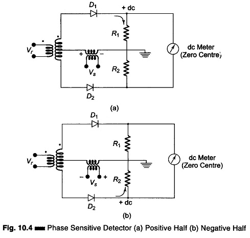
The Phase Sensitive Detector circuits of Figs 10.4(a) and (b) follows the action for a signal voltage Vs, which is in phase with the reference voltage Vr, starting with an initial condition when the input signal Vs is zero.
In Fig. 10.4(a), for the first half cycle the instantaneous polarity of the reference voltage Vr causes the rectified current to flow through the conduction rectifier D1, producing a positive voltage to ground across R1 and a tendency for the meter to deflect to the right.
On the second half cycle, Fig. 10.4(b), the instantaneous polarity of the reference voltage Vr, causes an equal rectified current to flow through diode D2, producing an equal tendency for the meter to deflect to the left. Since these two equal and opposite tendencies are averaged over the full cycle, the galvanometer reads zero over the full cycle, with input Vs = 0.
When an input signal Vs is applied, it either aids or opposes the reference voltage, depending upon whether it is in phase or out of phase with it. If Vs is in phase with Vr, the signal voltage will aid the instantaneous ac voltage in the upper half of the transformer secondary, producing a larger current through D1 and a larger dc output voltage on the first half. D2 does not conduct unless Vs is greater than Vr, so that the voltage across R2 is the rectified result of Vs – Vr, and that across R1 is Vs + Vr.
On the other half cycle, the signal voltage is in the opposite direction. Diode D1 will not conduct in the upper half and the signal voltage will oppose the instantaneous ac voltage, to produce a smaller dc voltage across R2. The galvanometer therefore deflects to the right in proportion to the magnitude of the in-phase input signal Vs. Similarly, if Vs is 180° out of phase with Vr, the voltages add on the lower half on the transformer secondary, and the galvanometer deflects to the left in proportion to the magnitude of that input signal.