AC Voltmeter using Half wave Rectifier | AC Voltmeter using Full wave Rectifier | Multirange AC Voltmeter:
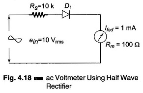
AC Voltmeter using Half wave Rectifier – If a diode D1 is added to the dc voltmeter, as shown in Fig. 4.18, we have an ac voltmeter using half wave rectifier circuit capable of measuring ac voltages. The sensitivity of the dc voltmeter is given by
![]()
A multiple of 10 times this value means a 10 V dc input would cause exactly full scale deflection when connected with proper polarity. Assume D1 to be an ideal diode with negligible forward bias resistance. If this dc input is replaced by a 10 V rms sine wave input. The voltages appearing at the output is due to the +ve half cycle due to rectifying action.
The peak value of 10 V rms sine wave is
![]()
The dc will respond to the average value of the ac input, therefore
![]()
Since the diode conducts only during the positive half cycle, the average value over the entire cycle is one half the average value of 8.99 V, i.e. about 4.5 V.
Therefore, the pointer will deflect for a full scale if 10 V dc is applied and 4.5 V when a 10 Vrms sinusoidal signal is applied. This means that an ac voltmeter is not as sensitive as a dc voltmeter.
As
![]()
The value of the multiplier resistor can be calculated as

AC Voltmeter using Full wave Rectifier:
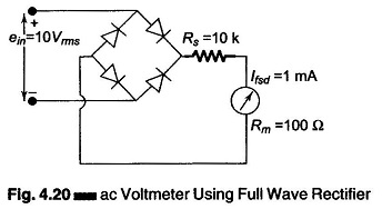
Consider the circuit shown in Fig. 4.20. The peak value of a 10 V rms signal is

Average value is

Therefore, we can see that a 10 V rms voltage is equal to a 9 V dc for full scale deflection, i.e. the pointer will deflect to 90% of full scale, or
![]()
Multirange AC Voltmeter:
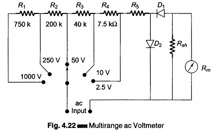
Figure 4.22 is circuit for measuring ac voltages for different ranges. Resistances R1, R2, R3 and R4 form a chain of multipliers for voltage ranges of 1000 V, 250 V, 50 V, and 10 V respectively.
On the 2.5 V range, resistance R5 acts as a multiplier and corresponds to the multiplier Rs shown in Fig. 4.17.
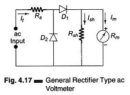
Rsh is the meter shunt and acts to improve the rectifier operation.