Single Phase Full Bridge Inverter:
The main drawback of half-bridge inverter is that it requires 3-wire dc supply. This difficulty can, however, be overcome by using a single phase full bridge inverter shown in Fig. 27.39 (a). It consists of four thyristors and four diodes. In this inverter, number of thyristors and diodes is twice of that in a half-bridge inverter. This, however, does not go against full-bridge inverter because the amplitude of output voltage is doubled whereas the output power is four times in this inverter as compared to their corresponding values in the half-bridge inverter. This is evident from Fig. 27.39 (b).
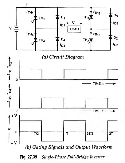
The sequence of thyristor gating and output waveforms are shown in Fig. 27.39 (b). Thyristors TH1 and TH2 must be gated simultaneously at frequency f = 1/T and thyristors TH3 and TH4 must be gated 180° out of phase with these. Frequency of output voltage can be controlled by varying periodic time T.
When thyristors TH1 and TH2 conduct, the load voltage VL will be positive i.e. V and when thyristors TH3 and TH4 conduct, the load voltage VL will be negative i.e. (- V) as depicted in Fig. 27.39 (b). Diodes D1, D2, D3 and D4 serve to supply the load reactive power back to the dc supply. As depicted in Fig. 27.39 (b), the output voltage waveform is fairly rectangular and remains unaffected by the nature of load. The circuit model of single phase full bridge inverter is same as illustrated in Fig. 27.38 (a).
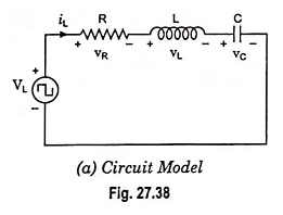
The load voltage and current waveforms for single phase full bridge inverter will be same as that shown in Fig. 27.38 (b) – (f), but the components conducting period will be different. In place of thyristor TH1, here two thyristors TH1 and TH2 conduct. Similarly, in place of TH2, thyristors TH3 and TH4 conduct and in place of diode D1, diodes D1 and D2 conduct, whereas instead of D2, here diodes D3 and D4 conduct.