Half Adder and Full Adder Circuit:
Adders are divided into two categories namely, half adder and full adder circuit.
Half Adder Circuit:
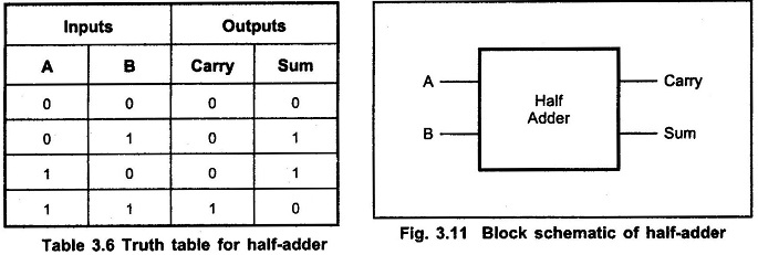
The Half Adder Circuit operation needs two binary inputs : augend and addend bits; and two binary outputs : sum and carry. The half adder truth table shown in 3.6 gives the relation between input and output variables for Half Adder Circuit operation.
Half Adder Truth Table:
K-map simplification for carry and sum:
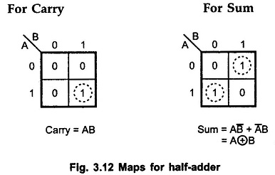
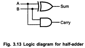
Half Adder Logic Diagram:
Full Adder Circuit:
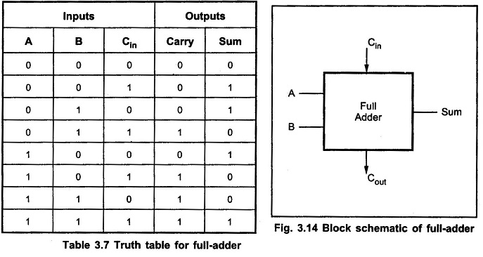
We have seen that a full adder is a combinational circuit that forms the arithmetic sum of three input bits. It consists of three inputs and two outputs. Two of the input variables, denoted by A and B, represent the two significant bits to be added. The third input Cin, represents carry from the previous lower significant position.
Full Adder Truth Table:
The Full Adder Truth Table is shown in Table 3.7.
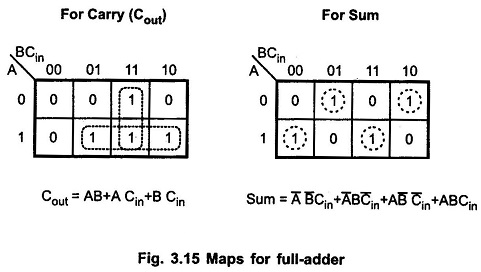
K-map simplification for carry and sum:
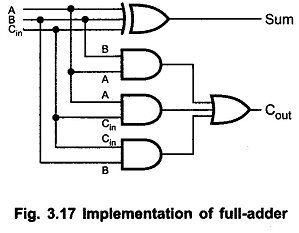
Full Adder Logic Diagram:
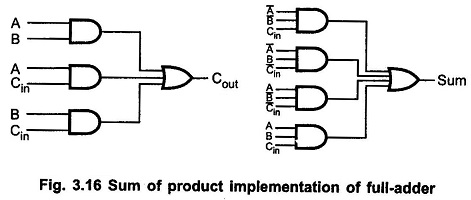
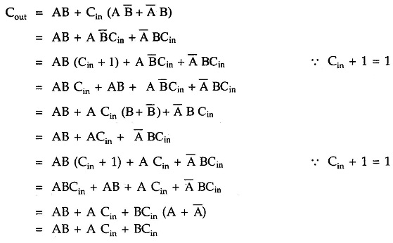
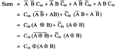
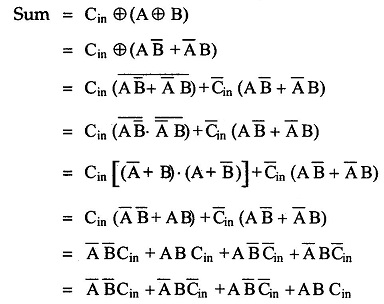
The Boolean Expression for sum can be further simplified as follows :
With this simplified Boolean function circuit for full-adder can be implemented as shown in the Fig. 3.17.
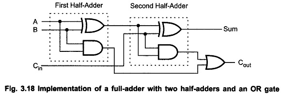
A full-adder can also be implemented with two half-adders and one OR gate, as shown in the Fig. 3.18. The sum output from the second half-adder is the exclusive-OR of Cin and the output of the first half-adder, giving
and the carry output is