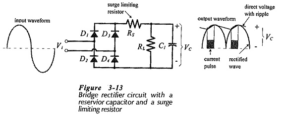
Full Wave Rectifier DC Power Supply:
Like half-wave rectifiers, full-wave rectifiers require filter circuits to convert the output waveform to direct voltage. Figure 3-13 shows a Full Wave Rectifier DC Power Supply with a reservior capacitor and a surge limiting resistor. These components operate exactly as explained for the half-wave rectifier circuit, with a few important exceptions.
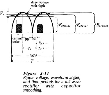
The capacitor-smoothed full-wave rectifier waveforms are shown in detail in Fig. 3-14. Equation 3-7, derived for the half-wave rectifier circuit, still applies for determining the angle θ1.
Eq. 3-7,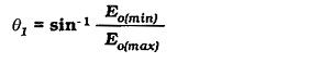
Also, θ2 can be determined from Eq.3-8,
Eq. 3-8,
![]()
and Eq. 3-9 can be used for time t2
Eq. 3-9
![]()
Comparing Fig. 3-14 and Fig. 3-8, it is seen that the capacitor discharge time (t1) for the half-wave circuit is approximately equal to the waveform time period (T), whereas for the full-wave circuit t1 approximately equals T/2. More precisely,
![]()
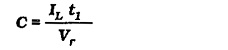
Using the correct value of t1, Eq. 3-11 can be used for calculating the reservior capacitance for a full-wave rectifier circuit.
Eq. 3-11,
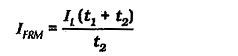
Similarly, (using the correct value of t1 in Fig. 3-14), the repetitive current (IFRM) can be determined from Eq. 3-15,
Eq. 3-15,
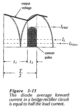
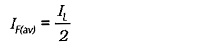
The average forward current passed by the bridge rectifier circuit is equal to the load current. But, each pair of diodes supplies current for no more than a half cycle of the input wave. The other pair conducts during the other half cycle. So, as illustrated in Fig. 3-15, the diode average forward current is half of the load current.
Another difference between the half-wave and full-wave rectifier power supply circuits concerns the reverse voltage applied to the diodes. Consider Fig. 3-16. When the instantaneous input voltage is +Vp, as illustrated, Vp is applied across forward-biased diode D1 in series with reverse-biased diode D3. Therefore, the reverse voltage across D3 is,
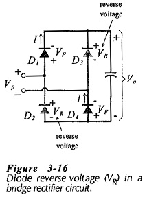
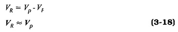
Examination of the circuit shows that Eq. 3-18 applies to each diode when reverse biased.
As in the case of the half-wave circuit, the capacitor calculation can be simplified by assuming that time t2 is very much smaller than t1. This gives the approximation that the capacitor discharge time is equal to half the input waveform time period.
![]()