Power Supply Decoupling:
Power Supply Decoupling – High-power amplifiers require high supply current levels, so unregulated power supplies are often employed to avoid the power wasted in a series regulator. The high ripple voltage that occurs with unregulated supplies can be amplified to appear at speaker outputs as very unpleasant power supply hunt Supply decoupling components CD and R15 are employed as shown in
Fig. 18-29(a) to combat hum. Capacitive impedance XCD forms an ac voltage divider with resistor R15, so that the ripple amplitude is attenuated, as illustrated. The resistance of R15 is usually selected approximately equal to emitter resistor RE1, and XCD is made very much smaller than R15 at the ripple frequency (fr). If XCD = R15/100 at fr, the, ripple voltage will be attenuated approximately by a factor of 100. The dc voltage drop across R15 must be taken into account when calculating VCC.
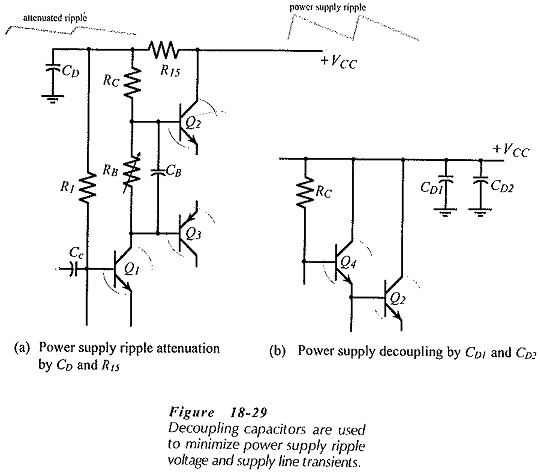
Figure I8-29(b) shows power supply decoupling capacitors (CD1 and CD2) without any series connected resistors. These are often used even when the supply voltages are regulated and hum is not a problem. When a sudden high output current is switched on or off the current change can produce short-lived (spike-type) voltage drops (transient) on the supply lines. These transients may be amplified to produce output distortion if they are allowed to appear at the supply lines for the first or second stages of a circuit. Capacitor CD1 is a relatively high-capacitance component that might normally be expected to perform the necessary decoupling.
However, such capacitors usually offer a relatively high impedance to high-frequency variations or fast transients. Consequently, the high-frequency low-capacitance component CD2 is required to ensure satisfactory decoupling. It is very important that decoupling capacitors be located right on circuit boards, as close as possible to the terminals of the circuit to be decoupled.
Increased Voltage Gain and Negative Feedback:
The Q1 collector resistor (RC) in the circuits discussed so far has its resistance limited by the need to supply base current to the npn output transistor. The resistance of RC also dictates the Q1 collector current level. This is shown by the IC1(dc) calculation.
A larger resistance for RC would give a greater voltage gain, which is desirable for negative feedback. It is shown that negative feedback reduces distortion and increases circuit bandwidth, so its use is necessary in all power amplifiers.
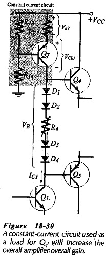
In Fig. 18-30 RC is replaced by a constant current circuit constituted by transistor Q7 together with emitter resistor RE7, and base bias resistors R13 and R14. The minimum level of VCE7 and the RE7 voltage drop are selected to equal the Q1 levels. This allows the voltage to the output stage to swing positively by the same amount as it can go negatively. The constant current circuit offers a high ac load resistance (1/hoe7) for the Q1 stage, to give the highest possible voltage gain.
Load Compensation:
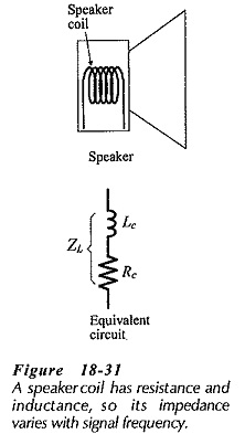
All design and analysis calculations for power amplifiers assume a resistive load with a given resistance value (RL). For audio amplifiers, the load is usually the coil of a speaker which, as illustrated in Fig. 18-31, combines coil inductance Lc and winding resistance RC. The load impedance is, ZL = Rc + j (2π f Lc), and clearly ZL increases (from a low of Rc at dc) as the signal frequency increases. An 8 Ω speaker might offer an impedance of 8 Ω only at a frequency around 400 Hz. The fact that the load is inductive means that the load current lags the load voltage, and typically the phase angle could be as high as 60°.
Similarly, when capacitive loads are involved the load current can lead the load voltage. The phase difference between load current and voltage can put stress on the output transistors, so output compensating components are often included to minimize the phase difference.
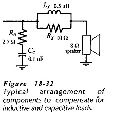
Figure 18-32 shows the typical arrangement of the compensating components. Inductor Lx and its parallel-connected resistor Rx are usually recommended by device and IC manufacturers for isolating a capacitive load. Capacitor Co and series-connected resistor Ro help to correct the lagging phase angle of an inductive load.