Clapp Oscillator – Circuit Diagram and Operation:
The Clapp oscillator shown in Fig. 21.15 is a refinement of the Colpitt’s oscillator. The single inductor found in the Colpitt’s oscillator is replaced by a series L-C combination [See L and C3 in Fig. 21.15]. Addition of capacitor C3 in series with L improves the frequency stability and eliminates the effect of transistor parameters on the operation of the circuit.
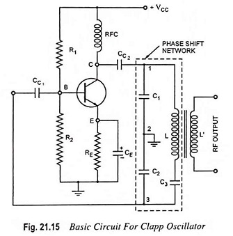
The operation of the circuit is the same as that of the Colpitt’s oscillator. As the circulating tank current flows through C1, C2 and C3 in series, the equivalent capacitance is
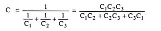
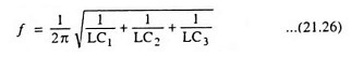
The frequency of oscillation is given as
Capacitors C1 and C2 are kept fixed while capacitor C3 is employed for tuning purpose.
In a Clapp oscillator C3 is much smaller than C1 and C2. As a result, the equivalent capacitance C is approximately equal to C3, and the frequency of oscillation is given as
![]()
However, precaution is to be taken in selection of C3. If capacitor C3 is made too small, the LC branch will not have a net inductive reactance and under such condition the circuit will refuse to oscillate.
In a Colpitt’s oscillator, the resonant frequency is affected by the transistor and stray capacitances because the capacitors C1 and C2 are shunted by the transistor and stray capacitances and so their values are altered. But in a Clapp oscillator, the transistor and stray capacitances have no effect on capacitor C3, so the oscillation frequency is more stable and accurate. This is the reason that Clapp oscillator is preferred over a Colpitt’s oscillator.
High frequency stability can further be obtained by enclosing the entire circuit in a constant temperature chamber and by maintaining the supply voltage constant with the help of a zener diode.