What is Resistor Transistor Logic (RTL) Circuit?
Resistor Transistor Logic (RTL) is a saturated logic and makes use of only transistors and resistors as circuit elements and also of resistors in the input to each base. This family is based on the NOR circuit. Its circuit diagram is shown in Fig. 47.1.
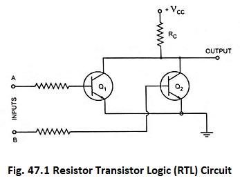
Assuming both transistors ideal when both inputs are low, both of the transistors are turned off and the output is high. If either or both input terminals are high, one or both transistors will be turned on and the output will be low. It is seen that the output is at logic 1 only when both inputs are at logic 0.
The RTL family is characterized by (i) poor speed (ii) low fan-in of 4 (iii) low fan-out of 6 (iv) higher power requirements (v) poor noise immunity and (vi) higher cost.
This technology, as already mentioned, has become obsolete.