What is Diode Transistor Logic (DTL) Circuit?
Diode Transistor Logic (DTL) is also a saturated logic and uses diodes, resistors and transistors. The circuit diagram is shown in Fig. 47.2. The basic DTL logic circuit is the NAND gate.
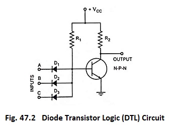
When inputs to all the three diodes are high, neither diode conducts and the transistor is turned on by the current provided by VCC through R1 and output is, therefore, low. If either or all inputs are low, the associated diode will conduct, the transistor will turn off and output is, therefore, high. It is seen that output is low only when all the inputs are high.
The family is characterized by (i) limited operating speed, (ii) fan-in of 8, (iii) fan-out of 5, (iv) low power consumption (v) poor noise immunity and (vi) highly temperature sensitive to threshold voltage.
As already mentioned, this technology has also become obsolete now.