Frequency Response of RC Coupled Amplifier:
The curve drawn between the voltage gain and signal frequency of an amplifier is known as the frequency response. The performance of an frequency response of RC coupled amplifier is judged to a considerable extent by its frequency response. In the design of an amplifier, appropriate steps are taken to ensure that gain is essentially uniform over some specified range.
Video amplifiers are almost invariably of the R-C coupled type. For such a stage the frequency response of RC coupled amplifier characteristics may be divided into three regions: Midband-frequency region, low-frequency region and high-frequency region.
In midband-frequency region, the amplification remains reasonably constant and equal to Avm. For the present discussion midband gain may be assumed to be normalized to unity, i.e., Avm = 1.
Low-Frequency Response: In the low-frequency region, below the midband, an amplifier stage behaves like the simple high-pass circuit (Fig. 16.5) of time constant τ1 = R1C1.
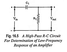
The current through the circuit is given by
![]()
and output voltage,
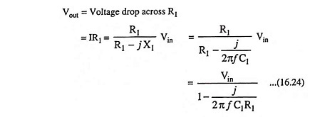
The voltage gain at low frequencies Avl, is defined as the ratio of the output voltage Vout, to the input voltage Vin.
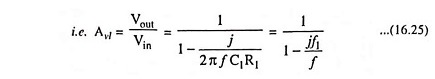
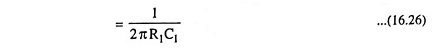
where f1 is the cutoff frequency and
Now magnitude of Avl and phase angle θ are given by
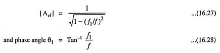
At the frequency f = f1, Avl = 1/√2 =0.707 whereas in the midband region (f >>f1), Avl → 1. Hence f1 is the frequency at which the gain has fallen to 0.707 times its midband value Avm. The drop in signal level (assuming equal input and output impedances) corresponds to a decibel reduction of 20 log 1/√2 or -3 dB. Accordingly, f1 is referred to as the lower 3-dB frequency. From Eq. (16.26) it is observed that f1 is that frequency for which the resistance R1 equals the capacitive reactance i.e. R1 = 1/2πf1C1.
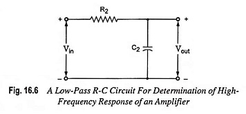
High-Frequency Response: In the high-frequency region, above midband, the stage behaves like a simple low-pass circuit shown in Fig. 16.6.
Proceeding as above, we obtain for the magnitude |Avh| and phase angle θ2 of the gain
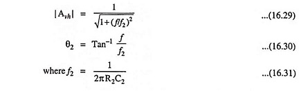
Since at f = f2 the gain is reduced to 1/√2 times its midband value, then f2 is called the upper 3-dB frequency. It also represents that frequency for which the resistance R2 is equal to the capacitive reactance 1/2πf2C2.
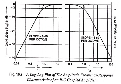
In the above expressions θ1 and θ2 represent the angle by which the output lags the input, neglecting the initial 180° phase shift through the amplifier. The frequency dependence of the gains in the high- and low-frequency range is to be seen in Fig. 16.7.
Bandwidth: The frequency range from f1 to f2 is called the bandwidth (BW) of the amplifier stage.