What is Inductor in Electronics?
An inductor has been defined as a physical device which is capable of storing energy by virtue of a current flowing through it. An Inductor in Electronics is a circuit component which opposes the change of current flowing through it and induces a voltage when the current flowing through it varies in magnitude and/or direction.
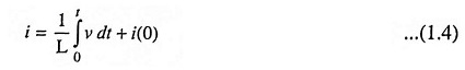
The circuit element used to represent the energy stored in a magnetic field is defined by the relation
![]()
The above expression describes a situation in which the voltage across the element is proportional to the time rate of change of current through it. The constant of proportionality L is the self-inductance or simply the inductance of the element, and is measured in henrys (abbreviated H).
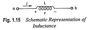
The voltage v in Eq. (1.3) is a voltage drop in the direction of current and can be considered to oppose an increase in current. Fig. 1.15 depicts the schematic representation of an inductance and its associated reference direction for current and voltage polarity.
Integrating Eq. (1.3) we have
where
- i(0) = Inductance current at t = 0.
According to Eq. (1.4) current through an inductance cannot change instantly (compared with capacitance voltage) as it would require infinite voltage.
Because the effect of inductance is to oppose the change in the magnitude of current, inductance is analogous to mass or inertia in a mechanical system and to the mass of liquid in hydraulics. Inductance prevents the current from changing instantly as it requires infinite voltage to cause an instantaneous change in current, just as the mass of an automobile prevents it from stopping or starting instantaneously.
The power associated with the inductive effect in a circuit is
![]()
and the energy stored is
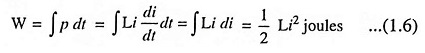
unlike the resistive energy, which is transformed into heat, the inductive energy is stored in the same sense that kinetic energy is stored in a moving mass. Eq. (1.6) reveals that the magnitude of stored energy depends on the magnitude of current and not in the manner of attaining that magnitude. The stored inductive energy reappears in the circuit as the current is reduced to zero. For example, if a switch is opened in a current carrying inductive circuit, the current decays rapidly, but not instantaneously. In accordance with Eq. (1.3), a relatively high voltage appears across the separating contacts of the switch, and an arc may form. The arc makes it possible for the stored energy to be dissipated as heat in the arc and the circuit resistances.
In case of an inductor, current does not change instantaneously. It offers high impedance to ac but very low impedance to dc i.e. it blocks ac signal but passes dc signal.
A piece of wire, or a conductor of any type, has inductance i.e. a property of opposing the change of current through it. By coiling the wire the inductance is increased as the square of the number of turns. The inductance is represented by English capital letter L and measured in henrys.
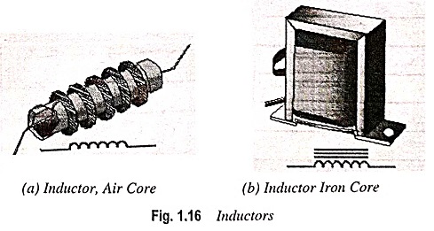
Specially made components consisting of coiled copper wire are called the inductors. Inductors are of two types viz., air-core (wound on non-ferrous materials) and iron-core (wound on ferrite cores). Inductors range in value from the tiny (few turn air-core coils of 0.1 μH used in high-frequency systems) to iron-core choke coils of 50 H or more for low-frequency applications. The symbols for air-core and iron-core inductors are given in Figs. 1.16 (a) and 1.16 (b) respectively.
The Inductor in Electronics can be classified into filter chokes, audio-frequency chokes and radio-frequency chokes.
Filter choke has many turns of fine wire wound on an iron core made of laminated sheets of E- and I-shapes and is used in smoothing the pulsating current produced by rectifying ac into dc. Generally power supplies use filter chokes having inductance ranging from about 1 H to 50 H, capable of carrying current up to 500 mA.
Audio frequency chokes (AFCs) are used to provide high impedance to audio frequencies (say 50 Hz to 5 kHz). These are smaller in size and have lower inductance in comparison to filter chokes.
Radio frequency chokes (RFCs) are employed to tune the radio frequencies (say, above 10 kHz). They are smaller than AFCs even. They have many turns of wire wound on an air core and very small value of inductance (about 2 mH).
For inductors, an approximate value of an inductance can be calculated from the following equation (as long as current is not so large that the linear region of B-H curve is exceeded)
where μ0 is the permeability of free space. μr is the relative permeability of the core material, N is the number of turns, a is the area of the core, and l is the length of the core.
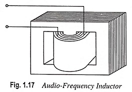
A typical audio-frequency inductor is shown in Fig. 1.17.
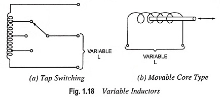
Variable Inductors: Some applications call for variable rather than fixed inductors. Tuning circuits, phase shifting, and switching of bands in amplifiers sometimes require a variable inductance. Such Inductor in Electronics can be made in different ways. Figure 1.18 illustrates how inductance is varied in several commercial elements. The inductor shown in Fig. 1.18 (a) can be varied by switching from one tap on the coil to another. In Fig. 1.18 (b) a movable core is used. As more of the core is inserted into the coil, the inductance increases. By appropriately varying the spacing of the coil windings a relatively linear variation of inductance with core insertion can be obtained.
The most common trouble in inductors is an open circuit, which can be checked with the help of ohmmeter. When the inductor is open, it cannot conduct current and, therefore, has no inductance. The ohmmeter reads infinite resistance for an open circuit. The inductor should be disconnected from the circuit while checking otherwise any parallel path may affect the ohmmeter resistance reading.
Colour Coding of Inductors: Colour codes are also used for small capacity moulded inductors for easy identification when they are mounted on printed circuit boards, known as PCBs. Colour coding scheme used is the same as for resistors.