Monochrome TV Transmitter – Block Diagram and its Workings:
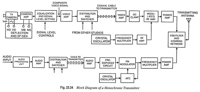
The term monochrome stands for black and white. Thus a monochrome TV system does not process variations of colour in a picture but processes only the intensity of brightness of each pixel for transmission in space. The picture is reproduced on the fluorescent screen of the monochrome picture tube in a receiver, in shades of white and black. At transmitter, picture carrier frequency assigned to the station is generated, amplified and later amplitude modulated with the incoming composite black and white signal. The sound output associated with the scene is simultaneously processed and frequency modulated with the channels and carrier frequency. The two outputs, one from the picture signal transmitter and the other from the sound signal transmitter are combined in a suitable network and then fed to a common antenna network for transmission. A functional block diagram of a Monochrome TV Transmitter is shown in Fig. 23.34.
Stages of Picture Signal Transmission:
Camera Tube : It converts optical image into electric charge image by using a photosensitive semiconductor target.
Deflection Circuit : The function of scanning is to convert the charge image into video signal, varying with time, to make it suitable for radio transmission. This is done by deflecting a well focused beam of electrons on the charge image horizontally and vertically. The deflection circuits are linear sawtooth signals. Scanning of one horizontal line takes 64 μs. Vertical scanning is relative slow and is completed in two sequences, each sequence is completed in 20 ms.
Blanking and Synchronizing Pulses : In the scanning process the linear ramp of sawtooth signal provides sweep or trace and the falling edge, also called flyback provides retrace. The retrace will distort the video signal, thus these are blanked by cutting off the beam using appropriate blanking pulses.
Synchronization pulses trigger the sawtooth generators at the correct instant of time to start scanning. Triggering of horizontal sweep generator is done by the leading edge of the H-sync and that of vertical sweep is done by a specified voltage attained by the vertical sync. Video signal combined with sync pulse and blanking pulse is called composite video signal. The purpose of transmitting the sync pulses along with the video signal is to use them to synchronize the sawtooth generator in the receiver with those in the Monochrome TV Transmitter.
Video Amplifier : It is a wideband amplifier and amplifies signals from a few Hz to 5.75 MHz. Composite video signal (CVS) is amplifier and gives sufficient power required for amplitude modulation. The video signal is made of negative polarity i.e. the white has low amplitude and the black, high amplitude.
DC Clamp : The inclusion of dc restorer circuit is required before the modulator.
Crystal Oscillator : A Monochrome TV Transmitter transmits at one allocated frequency and is called its channel frequency. The transmitted frequency should not drift and hence a crystal oscillator is used which produces highly stable frequency which is a sub-multiple of the actual allotted frequency.
Frequency Multiplier : Directly crystal oscillator cannot produce VHF or UHF range frequencies. Frequency multipliers are used to get the desired channel frequency (also called video carrier).
RF Amplifier : As the power level of RF carrier has to be high for TV broadcast systems, amplification stages are added to get the required level.
Modulated RF Amplifier : It receives amplified video signal and RF carrier and it is an amplitude modulator. The modulator is a nonlinear amplifier, which changes the amplitude of the RF carrier in accordance with the amplitude of the video signal. Since the video signal is of negative polarity, the achieved AM modulation is called negative modulation.
It causes saving in the transmitted power because in negative modulation white which is a dominant portion in a scene is of low level. It also makes the noise less perceptible in the reproduced picture at the receiver.
Vestigial Sideband Filter : The output of modulator is double sideband type, which is converted into vestigial sideband type by a sharp filter. The design of filter is such that it passes the carrier and upper sideband in full without attenuation. The lower sideband is produced upto 0.75 MHz below the carrier frequency, thus it is sharply attenuated. Therefore, the achieved signal is known as AMVSB signal. The use of AMVSB is to get more channels for transmission by reducing the overall bandwidth from 10 MHz to 5.75 MHz.
Stages of Sound Transmission:
Microphone : It converts the sound pressure variation into electrical signals, called audio signals. Widely used microphone in TV studio is dynamic microphone which uses the principle of electromagnetic induction for converting sound pressure variations into electrical signals.
Audio Amplifier : It is a RC coupled amplifier (class A type voltage amplifier) which amplifies the weak output of the microphone.
Pre-emphasis Circuit : It emphasizes the low energy of the high audio frequencies. The pre-emphasis enhances the frequency deviation, which results in high signal-to-noise ratio in FM systems.
FM Modulator : Before the power amplifier, low level modulation is used to save on the audio power requirements. Since a crystal is used to generate the carrier frequency, direct frequency modulation is not suitable because it is difficult to vary the frequency of a crystal. Armstrong method is used in which phase modulation of the crystal frequency is achieved. To convert the phase modulation into frequency modulation, change in phase is made dependent on the modulating frequency by an equalizing circuit. Thus we use the crystal for high stability and still we get frequency modulation. This is called indirect FM method.
Frequency Multipliers : The final frequency in VHF or UHF band allotted for transmission, is obtained by using multipliers and mixers. The final carrier frequency of the audio modulated FM wave is higher than the video carrier frequency by 5.5. MHz in CCIR B system followed in India and 4.5 MHz in CCIR M system used in USA.
Power Amplifier : The power of the frequency modulated signal is amplified to the required extent for transmission. This power is usually one fifth of the power required for AM video signal.
Combining Network : It is like a Wheatstone bridge, the two arms of which consists of two dipoles and the remaining two arms use reactive components like capacitor and inductor. Audio modulated FM signal is fed across the diagonal of the bridge and video modulated AM VSB signal to the other diagonal. This technique prevents isolation of the audio signal to the video signal and vice-versa.
Transmitting Antenna : A coaxial cable connects the combined output to the antenna system mounted on a high tower situated close to the Monochrome TV Transmitter. The transmitting antenna is generally a turnstile antenna. It consists of two dipoles perpendicular to each other and its directivity pattern is such that the radiation is omnidirectional in horizontal plane. For better signal-to-noise ratio the transmitting antenna is mounted horizontally.