Monochrome Television Transmitter:
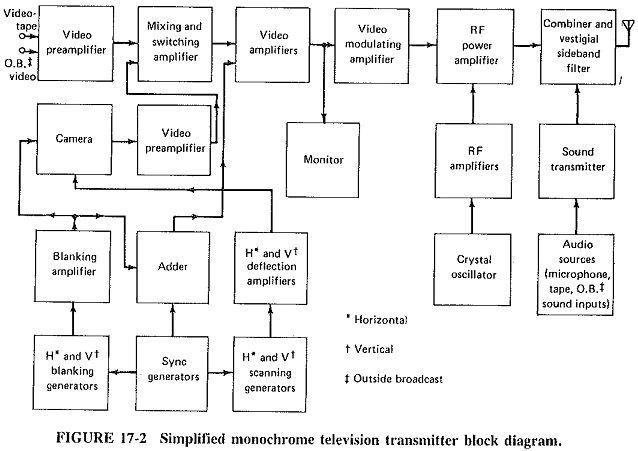
As shown in the block diagram of Figure 17-2, a Monochrome Television Transmitter system is quite unlike any of the transmission systems studied previously. This section will deal with the fundamental, “straightforward” blocks, while the functions specific to Monochrome Television Transmitter are described in more detail in the succeeding sections.
Camera Tubes:
The video sequence at the transmitting station begins with a transducer which converts light into (video) electric signals, i.e., a camera tube. Detailed descriptions of the various camera tubes are outside the scope of this chapter. Very basically, a camera tube has a mosaic screen, onto which the scene is focused through the lens system of the television camera. An electron gun forms a beam which is accelerated toward this photoelectric screen. The beam scans the screen, from left to right and top to bottom, covering the entire screen 30 times per second. The precise manner will be described in detail in the next section, and magnetic deflection, in connection with receiver picture tubes. The beam intensity is affected by the charge on the screen at that point, and this in turn depends on the brightness of the point. The current-modulated beam is collected at a target electrode, located at or just beyond the screen. The output voltage from this electrode is a varying (video) voltage, whose amplitude is proportional to the screen brightness at the point being scanned. This voltage is now applied to video amplifiers.
In color transmission, light is split into the three basic colors and applied to either three separate tubes or a single tube which has different areas sensitized to the different colors. The camera tubes most likely to be used are the vidicon or the plumbicon, in both of which separate tubes are required for the three colors. It is also possible to use a single camera tube which is constructed with a stripe filter or which uses three electron guns to produce all three colors at once.
Video Stages:
The output of the camera is fed to a video switcher which may also receive videotape or outside broadcast video signals at other inputs. The function of this switching system is to provide the many video controls required. It is at this point that mixing or switching of the various inputs, such as fading in of one signal and fading out of another, will take place. Videotapes corresponding to advertisements or station identification patterns will be inserted here, as well as various visual effects involving brightness, contrast or hue.
The output of this mixing and switching amplifier goes to more video amplifiers, whose function it is to raise the signal level until it is sufficient for modulation. Along the chain of video amplifiers, certain pulses are inserted. These are the vertical and horizontal blanking and synchronising pulses, which are required by receivers to control their scanning processes. The final video amplifier is the power amplifier which grid-modulates the output RF amplifier. Because certain amplitude levels in the composite video signal must correspond to specific percentage modulation values, this amplifier uses clamping to establish the precise values of various levels of the signal which it receives.
RF and Sound Circuitry:
Essentially, the sound transmitter is a frequency-modulated transmitter of the type. The only difference is that maximum deviation is limited to 25 kHz, instead of the 75-kHz limit for FM broadcast transmitters. The RF aspects of the picture transmitter are again identical, except that the output stage must be broad-band, in view of the large bandwidth of the transmitted video modulated signals. The output stage is followed by a vestigial sideband filter, which is a bandpass filter having a response. This is an LC filter, capable of handling the high power at this point. Its frequency response is critical and carefully shaped.
The output of the sound and picture transmitters is fed to the antenna via a combining network. This is in fact an LC equivalent of the circulator. Its function is to ensure that, although both the picture and sound transmitters are connected to the antenna with a minimum of loss, neither is connected to the other.