Television Horizontal Deflection Circuit:
The function performed by these circuits is exactly the same as already described for the vertical deflection circuits. There are some practical differences. The major one is the much higher horizontal frequency. This makes a lot of difference to the circuitry used by the horizontal oscillator and amplifier. Another important difference, as shown in the block diagram of Figure 17-9, is that the Television Horizontal Deflection Circuit output stage is used to provide the anode voltage for the picture tube. The current requirement is quite low, of the order of 800 μA. The voltage required is 10 to 18 kV. It must be produced somewhere in the receiver, and the horizontal output stage happens to be the most convenient point. The final difference between this and the vertical output section is quite minor but worth mentioning here. This is the fact that, since the aspect ratio of the picture tube favours the horizontal side by 4:3, the Television Horizontal Deflection Circuit current must be greater by the same amount.
Horizontal Oscillator and AFC:
Being much narrower than vertical sync pulses, and occurring at a much higher rate, horizontal pulses are a lot more susceptible to noise interference than vertical sync pulses. The latter contain a fair amount of power (25 percent modulation for just over 190 μs), and it is unlikely that random or impulse noise could ‘duplicate this. The output of the vertical sync separator may be used directly to synchronise the vertical oscillator, as was shown in the preceding section. Here the situation is different. A noise pulse arriving at the horizontal oscillator could quite easily upset its synchronization, through being mistaken for a horizontal sync pulse. The horizontal oscillator would be put out of synchronism, and the picture would break up horizontally. This is clearly undesirable. It is avoided in a practical TV receiver by the use of an AFC system which isolates the horizontal oscillator so that neither sync nor noise pulses actually reach it.
The AFC loop uses a Foster-Seeley discriminator. The output of the horizontal sync separator is compared with a small portion of the signal from the horizontal output stage. If the two frequencies differ, a dc correcting voltage is present at the output of the discriminator. When the two frequencies are the same, the output is zero. Note that the system depends on average frequencies instead of individual pulses.
Since the output of the horizontal AFC system is a dc voltage, the horizontal oscillator must be capable of being dc-controlled. This is certainly true of the blocking oscillator, which is one of the forms of the horizontal oscillator. If, in this so-called synchro-phase system, a dc voltage is applied instead of +18 V at the top of the Vhold control in Figure 17-18, frequency control with a dc voltage will be obtained. The reasoning is identical to that used in explaining the operation of the vertical hold control.
Multivibrators are also quite used as horizontal oscillators, and their manner of synchronization by a dc voltage is very similar to the blocking oscillator’s. The system is called synchro-guide. Recognizing that sinusoidal oscillators are somewhat more stable in frequency than pulse oscillators, some receivers use them. The system is then called synchro-lock, and the control voltage is applied to a varactor diode in the oscillator’s tank circuit.
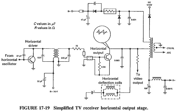
Horizontal Output Stage:
As in the vertical system; there is generally a driver between the Television Horizontal Deflection Circuit oscillator and the horizontal output stage. Its function is to isolate the oscillator and to provide drive power for the horizontal amplifier. It also matches the relatively high output impedance of the oscillator to the very low input impedance of the horizontal output stage, which is a high-power (about 25 W output) amplifier. The circuit diagram of a very simplified horizontal output amplifier is shown in Figure 17-19.
This is a highly complex stage, whose operation is now briefly indicated. The output transistor is biased in class C, so as to conduct only during the latter two-thirds of each line. It is driven with a sawtooth voltage, which is large enough to drive the output transistor into conduction from roughly one-third along the horizontal line to just beyond the start of the flyback. While the output stage is conducting, a sawtooth current flows through the output transformer and the horizontal yoke coils, so that the beam is linearly deflected. Meanwhile the damper diode, D1, is nonconducting, since its cathode is positive with respect to its anode.
The onset of the flyback promptly and vigorously switches off the output amplifier. If it were not for the damper diode, ringing would now begin, as previously explained in connection with the blocking oscillator. The typical frequency in the horizontal output transformer would be of the order of 50 kHz. What happens instead is that, as soon as flyback begins, the damper diode begins to conduct. This does not prevent the initial, negative-going half-cycle of oscillations. Since D1is conducting, the capacitor C is charged, and in this manner energy is stored in it, instead of being available for the ringing oscillations. The damper diode prevents all but the first half-cycle of oscillations and charges the capacitor C. The fact that the initial oscillatory swing took place is all to the good, because it helps to speed up the retrace.
At the end of the flyback C begins to discharge, through D1 and the primary of the horizontal output transformer. If conditions are suitably arranged, the current due to the discharge of this capacitor provides the scanning current to the horizontal yoke coils for the “missing” first one-third of each line. The advantage of doing this, instead of letting the output stage handle the whole scan (as was done in the vertical output stage), is that the maximum voltage rating and power handled by the horizontal output transistor are reduced by about one-third. Bearing in mind that, because of the 4:3 aspect ratio, more horizontal than vertical scanning power is needed. This system, though in practice somewhat more complicated than just described, is invariably used in practical TV receivers. Note that, just as in the vertical output stage, the Television Horizontal Deflection Circuit amplifier takes a large dc supply voltage, and that a small winding is provided on the output transformer for a comparison signal used in the horizontal AFC system.
The first half-cycle of oscillations after the flyback (the one not stopped by the damper diode) may reach a value in excess of 5 kV peak. This is boosted to 15 kV or more with the overwind, which is the additional winding in the output transformer, connected to D2. This HV (high-voltage) diode rectifies the pulse and derives a dc voltage from it which is applied to the anode of the picture tube. The filament voltage for this rectifier, as shown in Figure 17-19, is obtained from another (generally single-turn) winding on the horizontal output transformer. Note that the current requirement is under 1 mA, and consequently the power removed from the output stage in this manner is under 1.5 W.
The filtering of the HV rectifier output is obtained in a rather cunning manner. The filter resistor RF is generally very small, of the order of a few ohms. The filter capacitance CF is typically about 800 pF. Although these are quite small values, it must he remembered that the frequency is 15,750 Hz, and so these small values are sufficient. The cunning part of the proceedings is that Cp is not a capacitor. It is in fact the stray capacitance between the inner and outer (earthed) aluminized coatings of the picture tube, Note that if any of the Television Horizontal Deflection Circuit stages fails, so will this scheme, and the picture will disappear, since the picture tube anode voltage will have disappeared also.