Television Systems and Standards:
It is clear that a large amount of information must be broadcast by a television transmitter and that there are a variety of ways in which this can be done. Accordingly, a need exists for Television Systems and Standards for TV transmission and reception. Regrettably, no agreement has been reached for the adoption of worldwide standards, and it seems unlikely in the extreme that such a standard will ever be reached. Thus several different systems exist, necessitating standards conversion for many international television transmissions.
TV Systems:
Although agreement in certain respects is in some evidence, there are five essentially different Television Systems and Standards in use around the world. The two main ones are the American [Federal Communications Commission (FCC) system for monochrome and National Television Standards Committee (NTSC) system for color] and the European [Comite Consultatif International de Radio (CCIR) system for monochrome and Phase Alternation by Line (PAL) system for color.]
The American system is used in the whole of North and South America (except for Argentina and Venezuela) and in the Philippines and Japan. With some exceptions, the European system is used by the rest of the world. One of these exceptions is France, which, together with a part of Belgium, uses its own system, SECAM (sequential technique and memory storage), for color. The USSR and Eastern Europe use a system for monochrome that is almost identical to CCIR, but they use SECAM for color. With its greater line frequency, the French system has superior definition, but it requires a bandwidth twice as great as for the major systems. Table 17-1 shows the most important standards in the American and European systems. This is done for comparison. All subsequent detailed work will refer to the American system exclusively.
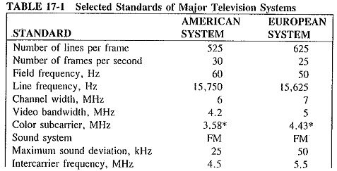
Apart from the differences, the two major TV systems have the following standards in common.
- Vestigial sideband amplitude modulation for video, with most of the lower sideband removed. This is done to save bandwidth.
- Negative video modulation polarity. In both systems black corresponds to a higher modulation percentage than white.
- 2:1 interlace ratio. This can be seen from the table, which shows that the field frequency is twice the frame frequency.
- 4:3 aspect ratio. This is the ratio of the horizontal to the vertical dimension of the receiver picture (or transmitter camera) tube. The absolute size is not limited, but the aspect ratio must be. Otherwise the receiving screen would not reproduce all the transmitted picture (or else a portion of the receiving screen would have nothing to show).
Notes on the Major American Television Systems and Standards:
The field frequency is purposely made equal to the 60-Hz frequency of the ac supply system, so that any supply interference will produce stationary patterns, and will thus not be too distracting. This automatically makes the frame frequency equal to 30 per second The number of lines per frame, 525, was chosen to give adequate definition without taking up too large a portion of the frequency spectrum for each channel. The line frequency is the product of 30 frames per second and 525 lines per frame, i.e., 15,750 Hz.
As we know, the channel width of 6 MHz is required to accommodate the wanted upper sideband, the necessary portion of the unwanted lower sideband, the FM sound frequency spectrum and the color subcarrier and its sidebands. The difference in frequency between the picture carrier and the sound carrier is precisely 4.5 MHz. This was given in Table 17-1 as the intercarrier frequency. The fact that this frequency difference is 4.5 MHz is used in extracting the sound information from the video detector.
In each TV channel, the picture carrier frequency is 1.25 MHz above the bottom edge of the channel, and the color subcarrier frequency is 3.58 MHz higher still. The sound carrier frequency is 4.5 MHz above the picture carrier frequency. Channels 2 to 13 are in the VHF band, with channels 2 to 6 occupying the frequency range 54 to 88 MHz, while channels 7 to 13 occupy the 174- to 216-MHz range. Note that the frequencies between 88 and 174 MHz are allocated to other services, including FM broadcasting. Channels 14 to 83 occupy the continuous frequency range from 470 to 890 MHz, in the UHF band.
Video Bandwidth Requirement:
The frequency band needed for the video frequencies may be estimated (actually, overestimated) as follows. Consider at first that the lowest frequency required corresponds to a line across the screen which is of uniform brightness. This represents a period of 1/15,750 = 0.0000635 = 63.5 μs during which the brightness of the beam does not change. If a large number of lines of that brightness followed in succession, the frequency during the time would be zero. This is too awkward to arrange, since it requires dc coupling. Thus the lowest frequency transmitted in practice is higher than zero, approximately 60 Hz in fact. As regards the highest required frequency, this will of course correspond to the highest possible variation in the brightness of the beam along a line.
Consider now that the picture has been divided into 525 lines from top to bottom, so that the maximum resolution in the vertical direction corresponds to 525 changes (e.g., from black to white) down the picture. It is desirable that horizontal and vertical resolution be the same, However, because of the 4:3 aspect ratio, the picture is 4/3 times as wide as it is high, so that 525 X 4/3 = 700 transitions from black to white during the length of a horizontal line is the maximum required. This, of course, corresponds to 700/2 = 350 complete (black-white-black) transitions along the line, occurring in 63.5 μs. The period of this maximum transition is thus 63.5/350 = 0.1814 μs. If each transition is made gradual (i.e., sine wave), rather than abrupt (square wave), 0.01814 μs is the period of this sine wave, whose frequency therefore is 1/0.1814 X 10-6 = 5.51 MHz.
The video bandwidth of 4.2 MHz quoted in Table 17-1 is quite enough. The reason for the difference is mainly that not all the 525 lines are visible. Several of them occur during the vertical retraces and are blanked out. Neither the vertical nor the horizontal resolution needs to be as good as assumed above, and so the maximum video frequency may be lower than the rough 5.51-MHz calculation. However, this calculation yields a reasonable approximation, and it does show that the bandwidth required is very large. This explains why vestigial sideband modulation is used.