Design of Current Carrying Capacity Systems:
The Current Carrying Capacity Systems of a circuit breaker consists not only of electrical conductors but also of mechanical devices like springs which do the dual job of passing the current as well as making and breaking contacts. In designing Current Carrying Capacity Systems it is, therefore, necessary to consider both the thermal problems like overheating and the electrodynamic problem due to the forces between conductors carrying current.
For calculating the electrodynamic forces we require information of linear dimensions of each element in the current carrying system, their physical location with respect to each other and maximum permissible current which is likely to flow through this system. The actual values of the forces exerted by different components on each other are generally calculated on the basis of grapho-analytical methods.
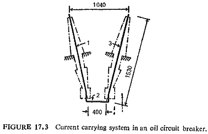
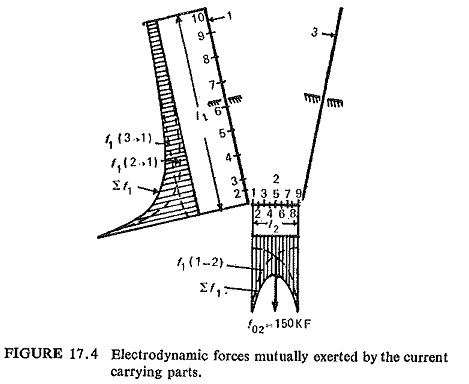
For example, Fig. (17.3) shows the Current Carrying Capacity Systems of the incoming conductor (1), the bridge (2) and outgoing conductor (3). Any two of these parts will be exerting forces on the third and the total force experienced by any part would be the sum of these two forces; this is clearly shown in Fig. (17.4). It will, therefore, be necessary while designing current carrying parts to consider not only their ability to carry current without overheating but also their mechanical strength to withstand the electrodynamic forces. If the latter is not properly taken into account, the contact system is likely to be distorted which will affect alignment of the fixed and moving contacts. This would result in the two contacts not locking properly and may create contact bounce.
Thermal Calculations:
Under this the following steps are generally indicated:
- Calculation of temperature rise under normal current for prolonged periods; and
- Temperature rise while carrying large fault current during very short periods.
From electrical point of view the Current Carrying Capacity Systems can be divided into two sections. One consists of incoming and outgoing conductors and other consists of main contacts. Incoming and outgoing conductors in the case of oil circuit breaker are located partly in oil and are surrounded partly by the bushings. While oil is a good conductor of heat, bushings are not. Thus part of the conductor is likely to be cooled faster than the other part producing thermal shocks on the material.
On the other hand, the lower part of conductor which is immersed in the oil is at much higher temperature than the outer part which is in the bushing. As for the conductors in the air-blast circuit breakers are concerned they are mostly enclosed by porcelain insulators which once again are bad conductors of heat. The insulators are, therefore, provided with many more petticoats than normal, to provide a greater surface area for radiating heat.
The contact system must reliably meet the following requirements:
- Temperature rise within the acceptable limits not only during normal operation but also when carrying through fault currents.
- Absence of local melting and globule formation.
- Absence of welding together of contacts particularly when closing them on a faulted line.
- Absence of film formation.