IIR Digital Filter Design Methods:
IIR Digital Filter Design Methods – Fettveis first suggested the use of one port reflection coefficients for the transfer of analog filter properties from the analog domain to the digital filter domain, and thus produced the wave digital filter structure.
Transformation of Passive Ladder Filter
The reason why reflection coefficients should be used is that a direct signal flow graph representation of the ladder in terms of its V-I relationship leads to structures in the digital filter domain using the bilinear transformation which are unrealizable, in that they contain loops without delay.
Basically a one port impedance Z, as shown in Fig. 15.33, can be described by its reflection coefficient
![]()
where
- R is an arbitrary reference resistance.
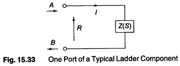
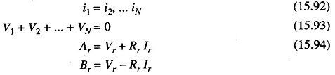
The numerator of Eq. (15.90), if delay free loops are to be avoided, must contain an overall factor of Z-1, that is it must vanish for Z-1 = 0. Hence we must have![]()
Thus all impedances of a ladder can be treated as one port and suitably transformed. Equation (15.91) needs to be applied with different values of R to all ladder impedances.
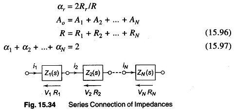
The interconnection of these one ports however requires an impedance level adjustment which in the Fettveis nomenclature corresponds to an adapter. For example, if we take the series situation of Fig. 15.34 with R1….RN as shown, the interconnections means that
(r = 1,… N) and hence
![]()
where
The digital structure realizing these conditions is known as a series adapter, and is represented symbolically as in Fig. 15.35.
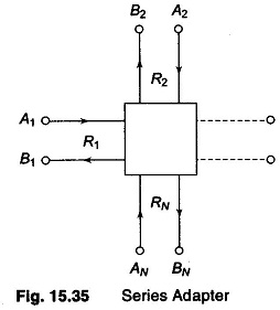
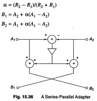
Similar structures can be derived for parallel connection of one port. A two port series-parallel adapter is shown in Fig. 15.36. It facilitates the interconnection of two ports of different normalization resistances.
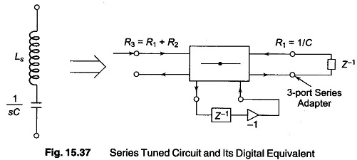
A simple example of a series tuned circuit equivalent is shown in Fig. 15.37.
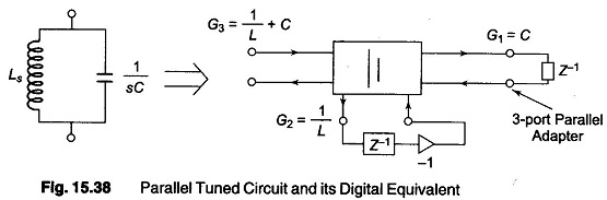
A parallel tuned circuit and its digital equivalent are shown in Fig. 15.38.
Digital structure realisation theory has also been applied to derive the filter of Fig. 15.39, where the original passive filter is also shown.
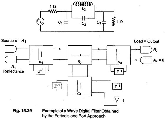
Note that the digital realization structure requires adders, multipliers and delays. The number of delays, of course, is consistent with the number of storage elements of the original passive filters. A more direct approach to wave digital filters is to treat the ladder elements of the passive ladder as two ports. In that case we need floating impedance and shunt admittances to realize a ladder.