Signal Conditioning System:
Signal Conditioning System – The measurand, which is basically a physical quantity, is detected by the first stage of the instrumentation or measurement system. The first stage is the detector transducer stage. The quantity is detected and converted or transduced into an electrical form in most cases. The output of the first stage has to be modified before it becomes usable and sufficient to drive the signal indicating stage which is the last stage. This last stage may consist of indicating, recording, displaying and data processing elements, or may consist of control elements.
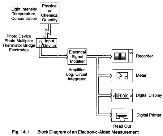
In an electronic-aided measurement, the quantity to be measured is converted into an electrical signal and then amplified or otherwise modified to operate a device which displays the numerical value of the measured quantity. This process is illustrated for a typical case in the pictorial block diagram shown in Fig. 14.1.
An input device such as a photo detector, thermistor bridge, glass pH electrode or strain gauge circuit is used to convert the quantity to be measured into an electrical signal. Some characteristic of this signal is related in a known way to the quantity to be measured. The measured quantity is now encoded as an electrical signal. The electrical signal from the input device is then modified by suitable electronic circuit to make it suitable for operating a read-out device. The electronic circuit is frequently an amplifier with the appropriate adjustable parameters (zero, standardisation, position, etc.) and sometimes with automatic compensation for non-linearities, temperature variation, etc. of the input device. It is a truism that the end result of any measurement is a number. (An electrical signal is an electrical quantity or a variation in an electrical quantity that represents information).
The output number is obtained from a readout device such as a meter or chart recorder, where the position of a marker against a numbered scale is observed, or from lights in the shape of numbers which are turned ON.
In Fig. 14.1 the measured quantity was encoded in at least three different ways. First, as a physical or chemical quantity or property, second, as some characteristic of electrical signal, and finally as a number. Each way in which data can be encoded is called a data domain. (Measurement data are represented in an instrument at any instant by a physical quantity, a chemical quantity, or some characteristic of an electrical signal. Each different characteristic or property used to represent data is called a data domain).
Measurement of dynamic physical quantities requires faithful representation of their analog or digital output obtained from the intermediate stage (signal conditioning stage) and this places a severe strain on the Signal Conditioning System.
The Signal Conditioning System may be required to perform linear processes such as amplification, attenuation, integration, differentiation, addition or subtraction. They are also required to do non-linear processes such as modulation, demodulation, sampling, filtering, clipping and clamping, squaring and linearizing or multiplication by another function. These functions require proper selection of components and faithful reproduction of the final output for the presentation stage.
The Signal Conditioning System or data acquisition equipment is in many cases an excitation and amplification system for passive transducer, or an amplification system for active transducer. In both cases, the transducer’s output is brought to the required level to make it useful for conversion, processing, indicating and recording.
Excitation is needed only for passive transducers, because they do not generate their own voltage or current. It is essential for passive transducers like strain guage, potentiometers, resistance thermometers, and inductive or capactive transducers to be excited from an external source.
Active transducers such as thermocouples, piezo-electric crystal and inductive pickups etc. do not require an external excitation because they produce their own voltages only by the application of physical quantities. However these signals are at a low level, and require amplification.
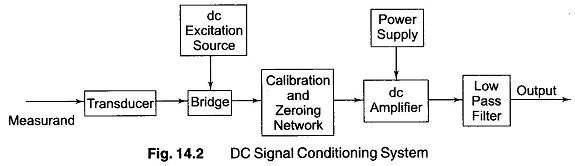
The excitation source may be ac or dc. A simple dc system is shown in Fig. 14.2.
The strain gauge (resistance transducer) constitutes one or more arm of the Wheatstone’s bridge, which is excited by the dc source. The bridge can be balanced by using a potentiometer and can also be calibrated to indicate the unbalanced condition. The dc amplifier should have the following characteristics.
- Its input stage may be a balanced differential inputs giving a high CMRR.
- It should have extremely good thermal and long term stability.
- Easy to calibrate at low frequency.
- Able to recover from an over load condition, unlike an ac system.
The main disadvantage of a dc amplifier is the problem of drift. Hence low frequency spurious signals are available as data at the output and to avoid this low drift of a dc amplifier, special low drift dc amplifiers are used.
The dc amplifiers is followed by a low-pass filter, which is used to eliminate high frequency components or noise from the data signals.
In order to overcome the problem of drift in the dc systems, ac systems are used. Figure 14.3 shows a circuit of an ac system using carrier type ac Signal Conditioning System.
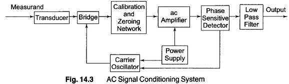
The transducers used are of the variable resistance or variable inductance type. They are employed between carrier frequencies of 50 kHz and 200 kHz. The carrier frequencies are much higher, at least 5 to 10 times the signal frequencies.
The output of a transducer is applied to the bridge circuit, whose output is an amplitude modulated carrier signal. This waveform is amplified by an ac amplifier. This amplified modulated output is then applied to a phase sensitive demodulator, the carrier signal. This produces a dc output that indicates the direction of the parameter change in the bridge output.
In a carrier system amplifier, frequency drift and presence of spurious signals are not much of a problem. However it is more difficult to obtain a stable carrier oscillator than a dc stabilized source. Active filters can be used to reject this frequency and prevent overloading of the ac amplifier. The function of the phase sensitive detector is to filter out the carrier frequency components of the data signal.
To summaries, dc systems are generally used for common resistance transducers (such as potentiometers and resistance strain gauges).
AC systems are used for variable reactance transducers and for systems where signals have to be transmitted via long cables to connect the transducers to Signal Conditioning System.
After physical quantities like temperature, pressure, strain, acceleration, etc. have been transduced into their analogous electrical form and amplified to sufficient current and voltage levels (say 1 – 10 V), they are further processed and the amplified signal applied directly to the indicating, recording or control systems.
The signal may be applied to a Sample-Hold (S/H) circuit, as shown in Fig. 14.4. This may be fed to an analog multiplexer and A/D converter. If the signal is in digital form, it may be applied to a variety of digital systems, such as computer, digital controller, digital data loggers, or transmitters.
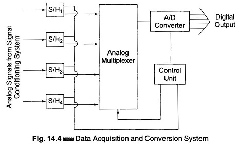
The Sample-Hold unit shown in Fig. 14.4 samples the various inputs at a specified time and holds the voltage levels at their output while analog multiplexer performs the Time Division Multiplexing (TDM) operation between different data inputs.
TDM means each channel is sequentially multiplexed for a certain specified time, i.e. each channel is time shared. The timing of various input channels is controlled by a control unit. This unit controls the S/H circuit, multiplexer and A/D converter.