Phase Locked Loop Working Principle:
A Phase Locked Loop Working is basically a closed loop system designed to lock the output frequency and phase to the frequency and phase of an input signal. It is commonly abbreviated as Basics of PLL.
The PLL was first introduced in its discrete form in early 1930s. The high cost of realizing Phase Locked Loop Working in discrete form, limited its use earlier. Now with the advanced IC technology, PLLs are available as inexpensive monolithic ICs. They are used in applications such as frequency synthesis, frequency modulation/demodulation, AM detection, tracking filters, FSK demodulator, tone detector etc.
The balanced modulator is an excellent building block for communication equipments. It can be used as a amplitude modulator, product detector, amplitude demodulator, mixer, frequency doubler, frequency detector and phase detector.
PLL Block Diagram:
Fig. 2.123 shows the PLL block diagram.
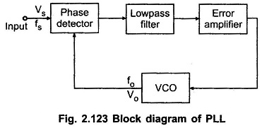
It consists of
- Phase detector
- Low pass filter
- Error amplifier
- Voltage Controlled Oscillator (VCO)
The phase detector compares the input frequency fi with the feedback frequency fo and generates an output signal which is a function of the difference between the phases of the two input signals. The output signal of the phase detector is a dc voltage. The output of phase detector is applied to low-pass filter to remove high frequency noise from the dc voltage. The output of low pass filter without high frequency noise is often referred to as error voltage or control voltage for VCO.
When control voltage is zero, VCO is in free running mode and its output frequency is called as centre frequency fo. The non-zero control voltage results in a shift in the VCO frequency from its free-running frequency, fo to a frequency f, given by
f = fo + KV VC
where KV is the voltage to frequency transfer coefficient of the VCO. The error or control voltage applied as an input to the VCO, forces the VCO to change its output frequency in the direction that reduces the difference between the input frequency and the output frequency of VCO.
This action, commonly known as capturing, continues till the output frequency of VCO is same as the input signal frequency. Once the two frequencies are same, the circuit is said to be locked. In locked condition, phase detector generates a constant dc level which is required to shift the output frequency of VCO from centre frequency to the input frequency. Once locked, PLL tracks the frequency changes of the input signal. Thus, a Phase Locked Loop Working goes through three states. : free running, capture and phase lock.