Phase Locked Loop Control(PLL):
A PI controller ideally should provide perfect speed regulation. However, due to imperfections in sensing and control circuits, the closed-loop schemes described earlier can at best achieve a speed regulatio of 0.2%. The Phase Locked Loop Control (PLL) can achieve a speed regulation as low as 0.002% which can be useful in conveyers for material handling, paper and textile mills, and computer peripherals.
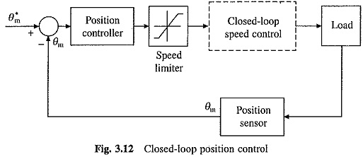
The Phase Locked Loop Control are available as inexpensive integrated circuits. Their circuit is shown in Fig. 3.11(a). Two pulse trains reference pulse train of frequency f * and the feedback pulse train of frequency f are compared in a phase detector. Output of the phase detector produces a pulse-width modulated output Vc. Pulse-width of Vc depends on the phase difference between the two input pulse trains and polarity depends on the sign of phase difference (i.e. lag or load) between them.
The output of the phase detector is filtered by the loop filter to obtain a dc signal and applied as control voltage to a voltage controlled oscillator (VCO); the output of which is the feedback signal f. Because of the closed-loop, VCO output frequency changes in a direction that reduces the phase difference. When steady state is reached, f becomes exactly equal to f* and the loop is said to have locked.
Control voltage required by VCO to produce f equal to f* comes from the phase difference between the two input signals. If now f* is altered, f will follow the change and control voltage required by VCO will be obtained by the adjustment of phase difference between the two input signals.
An electrical drive employing Phase Locked Loop Control is shown in Fig. 3.11(b). The VCO is replaced by converter, motor and speed encoder. Output of the loop-filter forms the control signal for the converter. It alters the converter operation such that the motor speed adjusts to make the frequency of speed encoder output signal f equal to the frequency of reference signal f*. By changing f* the motor speed can be changed.
Excellent speed regulation is the main feature of this drive. However, it has two important disadvantages: transient response is slow and it has a low speed limit below which it becomes unstable.
Closed Loop Position Control:
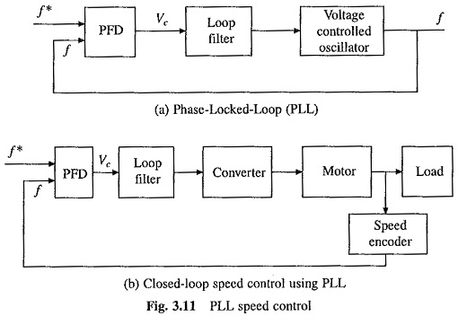
A Closed Loop Position Control scheme is shown in Fig. 3.12. It consists of a closed-loop speed control system with an inner current control loop inside an outermost position loop. Current and speed-loop restrict the current and speed within safe limits, enhance the speed of response, reduce the effects of nonlinearities in the converter, motor and load (such as nonlinear transfer characteristic of converter, coulomb friction, variation of parameters due to temperature and friction) on the transient and steady state performance of the position control system. Position controls are required in a number of drive applications, e.g. feed drive in machine tools, schrew down mechanism in rolling mills.