Closed Loop Speed Control of Induction Motor Drives:
A Closed Loop Speed Control of Induction Motor Drives is shown in Fig. 6.43. It employs inner slip-speed loop with a slip limiter and outer speed loop. Since for a given current, slip speed has a fixed value, the slip speed loop also functions as an inner current loop. Further it also ensures that the motor operation always occurs on the portion of speed-torque curve between synchronous speed and the speed at the maximum torque for all frequencies, thus ensuring high torque to current ratio. The drive uses a PWM inverter fed from a dc source, which has capability for regenerative braking and four-quadrant operation. The drive scheme is however applicable to any VSI or cycloconverter drive having regenerative or dynamic braking capability. The drive operation is explained below.
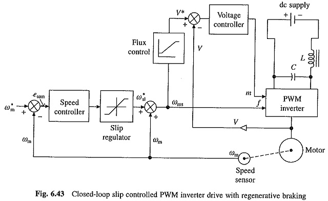
The speed error is processed through a PI controller and a slip regulator. PI controller is used to get good steady-state accuracy, and to attenuate noise. The slip regulator sets the slip speed command ω*sl, whose maximum value is limited to limit the inverter current to a permissible value. The synchronous speed, obtained by adding actual speed ωm and slip speed ω*sl, determines the inverter frequency. The reference signal for the Closed Loop Speed Control of Induction Motor Drives of the machine terminal voltage V* is generated from frequency f using a function generator. It ensures nearly a constant flux operation up to base speed and the operation at a constant terminal voltage above base speed.
A step increase in speed command ω*m produces a positive speed error. The slip speed command ω*sl is set at the maximum value. The drive accelerates at the maximum permissible inverter current, producing the maximum available torque, until the speed error is reduced to a small value. The drive finally settles at a slip speed for which the motor torque balances the load torque.
A step decrease in speed command produces a negative speed error. The slip speed command is set at the maximum negative value. The drive decelerates under regenerative braking, at the maximum permissible current and the maximum available braking torque, until the speed error is reduced to a small value. Now the operation shifts to motoring and the drive settles at the slip speed for which the motor torque equals the load torque.
The drive has fast response because the speed error is corrected at the maximum available torque. Direct control of slip assures stable operation under all operating conditions.
For operation beyond the base speed, the slip speed limit of the slip regulator must be increased linearly with the frequency until the breakdown value is reached. This is achieved by adding to the slip regulator output an additional slip speed signal, proportional to frequency and of appropriate sign. For frequencies higher than the frequency for which the breakdown torque is reached, the slip speed limit is kept fixed near the breakdown value.
When fast response is required the maximum slip can be allowed to be equal to sin, because induction motors can be allowed to carry several times the rated current during transient operations of short duration. The inverter and its front end converter are built using semiconductor devices whose transient and steady-state current ratings are the same. Then the ratings of inverter and front end converter will have to be chosen several time the motor current rating. This will substantially increase the drive cost. When fast transient response is not required, current ratings of inverter and front end converter can be chosen to be marginally higher than that of motor.