Speed Control of Variable Frequency Induction Motor:
Speed Control of Variable Frequency Induction Motor of a squirrel cage induction motor can be controlled very effectively by varying the stator frequency. Further, the operation of the motor is economical and efficient, if it operates at very small slips. The speed of the motor is, therefore, varied by varying the supply frequency and maintaining the rotor frequency at the rated value or a value corresponding to the required torque on the linear portion of the torque-speed curve.
The control of a three-phase induction motor, particularly when the dynamic performance involved is more difficult than dc motors. The is due to
(a) Relatively large internal resistance of the converter causes voltage fluctuations following load fluctuations because the capacitor cannot be ideally large.
(b) In a dc motor there is a decoupling between the flux producing magnetising current and torque producing armature current. They can be independently controlled: This is not the case with induction motors. For obtaining dc motor characteristics, the stator current must be separated into two components. The method is rather involved.
(c)An induction motor is very poorly damped compared to a dc motor.
For operation of the motor at small slips, it must be limited to the linear portion of the torque-speed curve. It can be shown that the torque developed, is proportional to the square of the air gap flux, i.e.
To retain the maximum torque capability at all operating points the flux must be maintained at its rated value. To achieve this supply voltage must also be varied simultaneously with the frequency. One simple and approximate method is to vary the voltage proportional to frequency such that
![]()
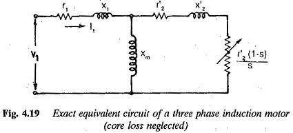
Using the equivalent circuit of the motor (Fig. 4.19) it can be derived that
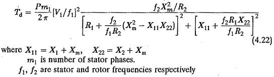
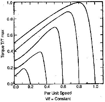
A family of curves showing the variation of torque with rotor frequency f2 with the stator frequency f1 as a parameter is shown in Fig. 4.20. From the expression as well as figure it is clear that at a given f2 the developed torque decreases at small stator frequencies. The maximum torque developed also decreases. This is because at smaller stator frequencies, the stator resistance drop becomes a large part of the applied voltage. Consequently the air gap flux decreases, causing a depletion of torque developed at a given f2, as well as maximum torque.
This control would be sufficient in some applications requiring variable torque, such as centrifugal pumps, compressors, and fans. In these, the torque varies as the square of the speed. Therefore at small speeds the required torque is also small and V/f control would be sufficient to drive these loads with no compensation required for resistance drop. This is true also for the case of the liquid being pumped with minimal solids.
However, in certain applications the pumps may require high starting torque. The torque developed with V/f constant may not be sufficient. In such cases the motor must be operated to provide its full torque capability at all frequencies. The motor must be supplied with an increased voltage to maintain the flux constant. Therefore the applied voltage to the Variable Frequency Induction Motor has two components at tow frequencies:
1.proportional to stator frequency
2.to compensate for the resistance drop in the stator.
The second component depends on the load on the motor and hence on rotor frequency. A voltage boost proportional to slip frequency may be applied. i This drive is the well known slip controlled drive.
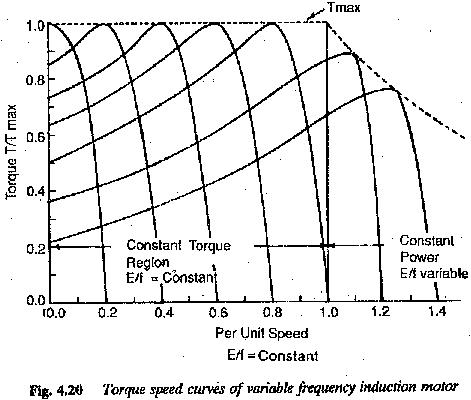
The method of maintaining the flux constant by providing a voltage boost proportional to slip frequency is a kind of indirect flux control. This method of flux control is not desirable if very good dynamic behaviour is required. Direct flux control is required if better dynamic behaviour is required. This can be achieved by direct measurement of flux using search coils or calculation of the flux using machine parameters, voltages and currents. In the former the machine loses its robust nature whereas in the latter the errors are introduced due to the use of inaccurate parameters obtained from no-load tests. In all these methods the applied voltage V1 is varied such that E/f is constant at all operating points, to maintain the air gap flux at its rated value. The inverter used to supply an Variable Frequency Induction Motor must be capable of providing a variable voltage, variable frequency supply. The control used must be such that the air gap flux is constant at all operating points. The speed torque curves of the motor for this type of control are shown in Fig. 4.20(b).