Three pulse midpoint converter:
These are basically three-phase converters, and are very popular because a 3-phase supply is readily available. 3-phase converters have a greater power capability than single phase converters. With these converters the pulse number of the output voltage superimposing the mean dc voltage can be increased using suitable transformer connections. Increasing the number of pulses improves the converter performance with respect to the amplitude of the dc voltage as well as the magnitude of ripple content. The dc voltage of a Three pulse midpoint converter is more, with reduced ripple content. Also, the smoothing inductance becomes small.
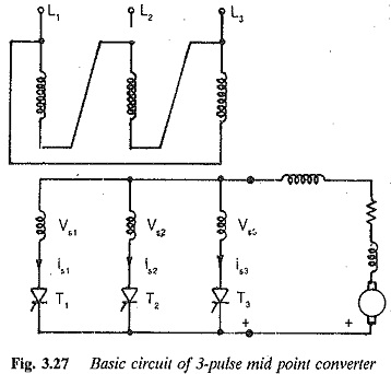
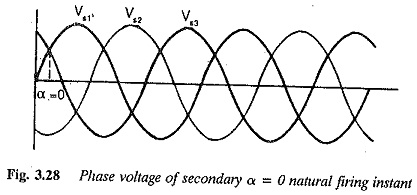
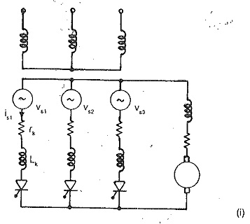
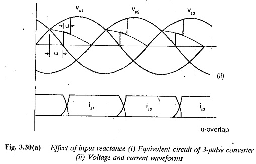
A Three pulse midpoint converter is the simplest form of a 3-phase converter. It is shown in Fig. 3.27. From the figure it is clear that the star point of secondary of the converter transformer is required to serve as a return path for the current. The converter is also called a star point converter. The output voltage can be varied steplessly by varying the firing angle of the thyristor. A thyristor which has forward voltage across it can start conducting if it receives a firing pulse. The phase voltages Vs1,Vs2 and Vs3 are shown in Fig. 3.28. From the figure, the natural firing point of the thyristor can be identified. It is the instant at which the diodes would start conducting if the converter were uncontrolled, and is the point of intersection of the voltages. This instant, at which a thyristor is forward biased, occurs 30° after its voltage has crossed zero. A thyristor can always go into conduction if it receives a firing pulse
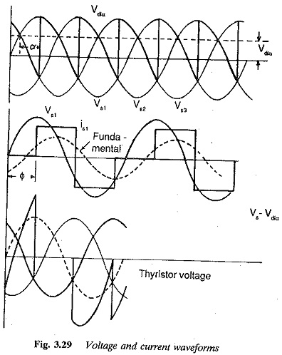
when its phase voltage is greater than that of the outgoing one. The firing angle is reckoned from this point. The phase voltage having the largest instantaneous value can only appear across the load. If the firing turning-on takes place at the natural firing instant, the mean voltage at the output terminals is a maximum. The voltage and current waveforms for several firing angles are shown in Fig. 3.29. Each thyristor conducts for 120° and blocks for 240°.
The maximum reverse voltage across a thyristor is the line to line voltage, which is equal to √3 times the phase voltage.
The average thyristor current is
The rms value of the thyristor current = 0.23 V ∕ R
The mean output dc voltage atany firing angle is given by
![]()
assuming instantaneous commutation. This equation is valid for continuous conduction of load current, i.e. the current should not become zero when the voltage is zero, as happens in a resistive load or back emf load. With sufficient inductance in the load circuit, the load current flows even when the voltage is negative.
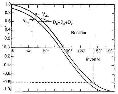
As the firing angle α increases from 0 to 90°, the output voltage falls from a maximum of 1.17V to zero very smoothly. The power flow takes place from ac to dc and the converter is in the rectifying mode. If the firing angle is increased further or retarded, the output voltage has a reversed polarity. Power flow can take place from dc to ac only if there is a source of dc voltage, e.g. a counter emf load, such as a dc motor load will be able to do this during regeneration. The converter is in the inverting mode. The output voltage increases progressively in the negative direction as a reaches 180°. Therefore for angles 0 < α < 90° the converter is in the rectifying mode and for 90° < α < 180° it is in the inverting mode. Normally the reverse voltage must exist across the thyristor for a time greater than its turn off time, so that it successfully goes into the forward blocking condition. The turn off time of a thyristor is of the order of 100 μs to 300 μs. When α = 180° the conducting thyristor can never be blocked, as there is no time at all for it to regain its blocking state. The time for which the reverse voltage exists across a thyristor must be greater than ωtq.
Also, the negative voltage occurring across the thyristor should continue even after the thyristors have under gone commutation for a definite amount of time tq. For successful commutation there should be a marginal turn off angle, and α = 180° cannot be realised. Figure 3.30 depicts the variation of output voltage as the firing angle is extended from 0-180°. (The control characteristic of the converter shown in Fig. 3.30 also shows the inverter limit.)
The finite angle of overlap, due to reactances on the line side of the converter, also affects the maximum firing angle for inverter operation. Taking these factors into consideration, the maximum, firing angle αmax is fixed at 150°.
Sometimes commutation failure occurs if the applied voltage is small. This increases the overlap which affects the inverter limit, making the lead angle of firing less than the sum of the overlap and turn off angle. Commutation troubles normally arise if circuit turn off is less than the turn off time of the thyristor. For successful commutation there must be a marginal quenching angle.
Under ideal smoothing conditions of dc load current the voltage Vdiα is dropped across the resistance and the superimposed ripple content across the load inductance.
A close examination of the primary and secondary currents of transformers shows that there is no mmf balance because of the dc component of current in the secondary winding. The dc mmf premagnetises the core. Each leg of the transformer carries a de flux, passing mainly through air. A heavy magnetising current is required by the transformer. Also, when the primary is star-connected there exists a third harmonic flux besides the dc flux. This produces additional losses and consequent heating of the transformer. It also induces additional voltages in the transformer windings. This harmonic flux does not exist in a Δ connection.
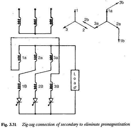
This dc and the third harmonic core flux can be completely eliminated by using a zig-zag connection, as shown in Fig. 3.31. In this connection the current of a thyristor is made to flow through the windings on different legs, so that the dc magnetisation and third harmonic flux get cancelled. However the rating of this transformer is 8% higher than one with a normal connection.
Even though the fundamental of the current decides the power used up in the dc side, the rating of the transformer must be decided using the total or actual current flowing through the winding.
RMS value of the secondary current Id ∕ √3.
The rating of the secondary winding
Overlap: The commutation of the current from one thyristor to the other is never instantaneous. The incoming and outgoing thyristors conduct simultaneously during commutation. The period of simultaneous conduction is called overlap. The angle of overlap depends upon the transformer leakage reactance, line reactances and any other inductances in the circuit which limit the di/dt of the thyristor. The overlap depends upon the load current and angle of firing. The dependence of overlap on angle of firing can be understood from the following equation
![]()
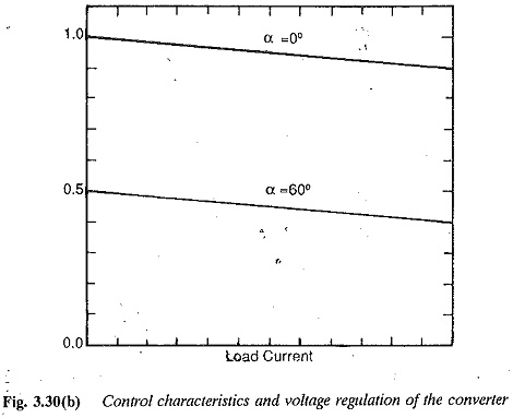
where uo is the overlap angle at α = 0 and u is the overlap angle at α. The effects of total reactance (Xk) and total circuit resistance, Rk, which is negligibly small on the terminal voltage can be derived in general. Due to overlap there is a reduction in terminal voltage. This can be attributed to the voltage drops in the reactances when there is a change of current. The voltage regulation and associated equations can be determined using the equations given for single phase connections.
The voltage drop due to overlap
The resistance drops and device drops in the forward direction also contribute to voltage regulation.
Therefore the terminal voltage
The control characteristic, taking regulation into consideration, is shown in
Fig. 3.30.
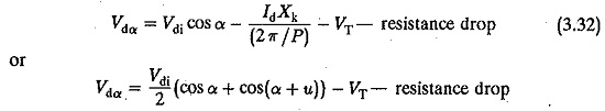
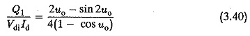
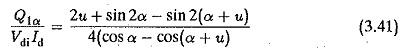
The mean dc voltage of the converter is superimposed by a non-sinusoidal ac voltage. It has a ripple of three times the supply frequency. The effective value of the rth harmonic referred to Vdi is
![]()
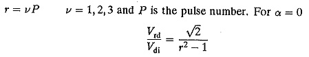
when the overlap is considered
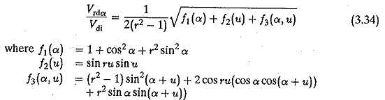
Defining the ripple content as the ratio of the effective value of superimposed ac voltage to ideal dc voltage, (Wu) we have
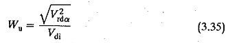
For a Three pulse midpoint converter, Wu is 18.3% for α = 0 and 65.5% for α = 90°.
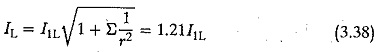
As has already been discussed, the inductance Ld smooths our the ripple content in the load current and helps to make it continuous. Under ideal smoothing, the load voltage is dropped across the resistance and the ripple voltage across Ld. Ld is normally determined such as to avoid discontinuous conduction. For a three pulse converter
![]()
where α is the firing angle and Id is the value at which the current becomes continuous
The input current of a Three pulse midpoint converter also has a harmonic content. The effective value of the rth harmonic is
![]()
which is 50%, 25% and 20% of the fundamental for r = 2, 4 and 5 respectively. The effective value of the line current
The effect of overlap iS to reduce the harmonic content
![]()
The converter requires reactive power for phase control as well as for commutation. This reactive power is supplied from the lines and affects the power factor of the input current. The harmonics in the current waveform contribute to the reactive power. The fundamental displacement factor is the cosine of the angle between the fundamental of the input current and the voltage. This and the fundamental current contribute to the active power. The total power factor is affected by the harmonics. Therefore the fundamental displacement factor must be corrected properly to obtain this altered power factor. A close . examination of the voltage and current waveforms reveals that the fundamental displacement factor is nothing but the cosine of the firing angle of the thyristors. For α = 0 the secondary phase voltage and the fundamental.current are in phase and the displacement factor is unity. As α increases, this factor decreases. The effect of harmonics on the amount of reactive power can be considered by taking into consideration their effect on the power factors. The distortion factor g is defined as the effective value of the fundamental to the effective value of the total current (I1 ∕ I). The total input power factor = g cosα. For Three pulse midpoint converter this is 0.827. As g is always less than one, the distortion decreases the total power factor.
The reactive power due to commutation can be determined using the following equation.
The total reactive power can be determined as a ratio of the dc power at any control angle, using
The fundamental displacement factor taking overlap into consideration is approximately cos(α + u/2) or cos(α + 2u/3) depending upon 60 < α < 90° or 0 < α < 30°.
Therefore, the total power factor = gcos(α + u/2) (3.42)
Transformer utilisation in controlled rectifiers: The expressions of device currents in midpoint converters discussed emphasize that the utilisation of devices as well as transformers decrease as the number of phases or pulses increases. The conduction angle decreases, adversely affecting the losses and current ratings of the devices. The ratio of the rms to average value of current increases, which increases the copper losses of the transformer. The utility of the transformer can be conveniently defined by the ratio of dc output power from the rectifier to the effective volt amperes of the transformer, or the design rating of the transformer, which is the average of the primary and secondary ratings of the windings. Under ideal conditions it may be unity, but is normally less than 1.
In the case of controlled rectifiers, the transformer utilisation decreases at reduced voltages in the same ratio as the power factor. This is evident from the voltage and current waveforms. We see that the firing angle variation introduces a phase shift in the current pulses, as compared to the uncontrolled case. This has no effect on the harmonics but changes the input displacement factor. The value of a also has no effect on the value of ac input current relative to dc output current. The reduction in power factor matches the reduction in output voltage and the necessary power balance is thus maintained. Therefore, at reduced voltage transformer utilisation reduces in the same ratio as the power factor.