Starting Method of Induction Motor:
Transient processes involved with the Starting Method of Induction Motor in a variable speed drive require a detailed study. The electric motor and connected load accelerates to the rated speed from rest under the influence of the starting torque. The transient operation during is satisfactory if a sufficiently good starting torque is developed with a reduced value of starting current, to accelerate the rotor in the desired amount of time.
The need to limit the starting current arises due to heavy dips of the voltage of the motor following starting peaks of current. The starting equipment used should be capable of minimising these dips in the voltage to a tolerable value, so that the other equipment on the network is not affected.
The starting current affects the motor also. High starting currents heat up the rotor. If starting is frequent, the heating needs to be reduced or limited. In dc machines high starting currents produce sparking at the brushes. For good commutation the starting currents must be limited.
In converter operation additional harmonics of current affect the commutation. These problems of commutation in dc motors due to ripple may be solved by (properly) increasing the pulse number of the power converter, and modifying the design of the motor itself, e.g. laminating the interpoles.
The starting torque must produce uniform acceleration. Acceleration time must be reduced with a view to improving the productivity and to reduce the energy lost during starting.
The purpose of starting equipment in an electric motor is to limit the starting current and to provide a reasonably good starting torque, if possible, so that the motor accelerates in the desired period to the rated speed. For dc motors the starting current is limited by using an additional resistance in series with the armature. The motor is switched on with full field. This is effectively reduced voltage starting. Thyristor power converters used for speed control may also be used for the purpose of starting, since the voltage is smoothly variable and starting losses are absent.
Starting Method of Induction Motor has the following methods:
- Direct on line starting
- Low voltage starting
- Rotor resistance starting
- Low frequency starting
- Special rotor construction.
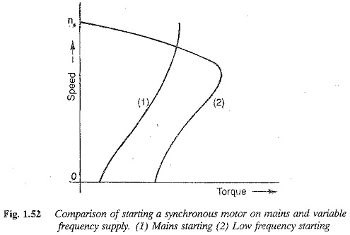
Synchronous motors are not self starting, but are started by an auxiliary motor or using the induction motor principle. The damper windings are used as starting windings. To make a synchronous motor self starting, a wound rotor is employed. It is short circuited with an additional resistance during starting and fed from a dc when accelerated to synchronous speed. A synchronous motor can also be started using a variable frequency inverter system. A comparison of variable frequency starting with mains starting is given in Fig. 1.52.
Energy Relations During Starting:
In order to select a proper starting equipment, e.g. the starting rheostat in a shunt motor, it becomes necessary to determine the energy loss during starting.
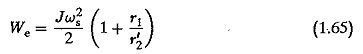
1.The energy loss during starting is the K.E. of the rotating parts at final speed. The same energy is drawn from the supply. Therefore the total electrical energy drawn from the supply during starting is
![]()
where
- ωs is the final speed at no-load.
When started against a load of torque TL the total loss in the armature circuit is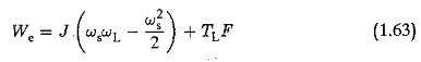
where ωL is the speed with load TL and TLF is the energy loss due to the load torque and is given by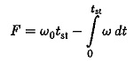
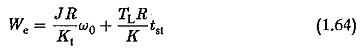
In the case of dc series motors the energy loss depends on R, and is given by
2.In the case of an Starting Method of Induction Motor, an additional rotor resistance is employed. The energy loss in the rotor resistance is the K.E. of the rotating parts. Part of the energy is dissipated in the stator resistance also. The total energy lost during starting is
An increase in rotor resistance decreases the energy loss in the stator resistance, whereas it does not affect the loss in the rotor resistance itself. This decreases the time of acceleration.
When the motor is started on load the loss dissipated is greater than at no-load, and is given by
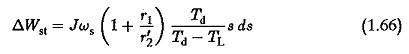
where Td and TL are functions of slip. The integration of ΔWSL from 0-ωs gives the total energy loss. When squirrel cage motors are started directly from the line, there is minimum energy dissipation because the torque developed is large with full voltage. With low voltage starting, Td decreases and the energy wasted increases, even though starting current decreases. This may be attributed to the increase of acceleration time at low voltage starting.
In squirrel cage motors the entire energy is lost in the machine itself, whereas in slip ring rotors an external resistance may be used for the dissipation of energy, thus minimising the motor heat but increasing the starting time.
Starting Dynamics of Electric Motor:
The starting of electric motor is normally done with graded resistances which are cut off slowly as the motor accelerates. The grading is based on two limits between which starting current is allowed to vary. The dynamics during starting may be necessary to actually find out the values of these resistances.
DC shunt motor:
When a shunt motor is accelerated under load, the equations are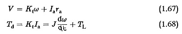
Using these relations we have
where
- ω0 is the no-load speed
- ωL is the speed drop under load
- Tm is the mechanical time constant.
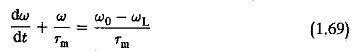
If the motor is accelerated from ω1 to ω2 the solution of this equation may be obtained as
![]()
If the acceleration is from zero to ω0 we have
![]()
During starting, the current drops as the motor speeds up, due to the building up of back emf. The armature current drops exponentially as![]()
where I1 is the starting current and IL the final value. If the acceleration is at no-load
![]()
The time of acceleration can be determined using these relations. If a multi-stepped starter is used, the time taken for the current to drop from I1 to I2 is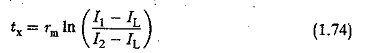
The mechanical time constant is different at different steps, and is given by
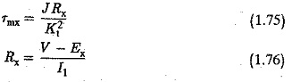
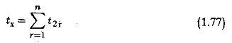
The value of Ex is obtained by using the value of speed, which increases exponentially. Finally, the total accelerating time
Induction motor:
We can analyse the transient conditions in a three phase induction motor with a view to determining the time of acceleration. It is well known that by properly adjusting the rotor resistance, maximum torque may be made to occur at starting. But analysis shows that this does not give the minimum time of acceleration, which is obtained if the rotor resistance is selected such that the maximum torque occurs at a slip of 0.407.
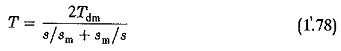
The torque developed at any slip is given by
Assuming the acceleration takes place at no-load, the torque developed accelerates the rotor
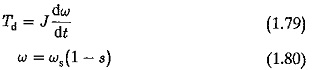
Also, we have assuming the no-load speed is synchronous speed. Using the above equations we have
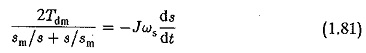
form which
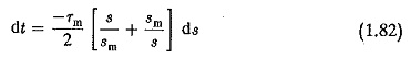
where Tm=Jωs∕Tdm is the mechanical time constant of the motor. The motor starts from rest and runs up to no-load speed. The slip varies from 1 to s. Integrating Eq. 1.82 between these limits we have
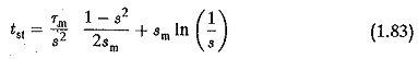
If the final slip is assumed to be s = 0.03, the starting time tst is
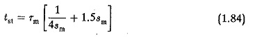
The minimum value of tst is obtained by
which gives sm = 0.407. The ratio tst∕Tm as a function of sm is shown in Fig. 1.51 To accelerate the rotor in the time tst the effective torque is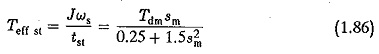
This shows again that the starting time is a minimum if the starting torque is 0.81 Tdm. This happens again if Tdm occurs at sm = 0.407. An Starting Method of Induction Motor can be made to accelerate in minimum time if the starting torque is 0.81 times the maximum torque and the maximum torque occurs at sm = 0.407.