Starting and Speed Control of DC Traction Motors:
Starting and Speed Control of DC Traction Motors – As already discussed, only series and compound dc motors are suitable for traction work. With a dc series motor, the current and torque produced at standstill may be reduced by strengthening the field or lowering the terminal voltage or both. Motors may be placed in series, reducing the terminal voltage of each without loss in external resistance. External resistance may be placed in series with the motors to limit the starting current to any desired value, and by varying the resistance the current may be kept constant during notching up period as desired, as the back emf is being built up. Since maximum torque while starting demands full field strength, any shunt or reduced field connections are usually thrown out of action in starting.
With the dc compound motor the start may be made with full armature current in the series field coils and maximum current in the shunt field coils. A starting resistance inserted in the armature circuit is reduced in steps until the armature and series field are connected across the line. Further speed increase is affected by reducing the shunt field current in steps to the point where the shunt field winding is disconnected, and the action is then identical with that of a plain series motor.
Various methods used for starting and speed control of DC traction motors are discussed below.
1. Rheostatic Control
A series motor can be started by connecting an external resistance (starter) in series with the main circuit of the motor. At the starting instant, since the back emf developed by the motor is zero, therefore, the resistance connected in series with the motor is maximum and is of such a value that the voltage drop across it with full load rated current is equal to line voltage. As the motor speeds up, the back emf developed by the motor increases, therefore, the external resistance is gradually reduced in order to maintain the current constant throughout the starting or accelerating period. Basic traction motor circuit with rheostatic starting is shown in Fig. 13.1. In this method there is a considerable loss of energy in the external circuit.
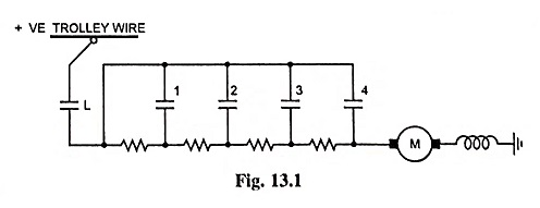
The resistors employed are designed for short-time rating and not for continuous rating as they are required to carry current only during starting of motors. The motor can, therefore, have only one speed characteristic.
2. Series-Parallel Control
The main disadvantage of wastage of electrical energy in rheostatic control is partly overcome in this method when there are two or more motors.
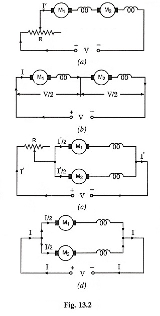
In case of two motors, the motors are first connected in series with each other and a starting or control resistance as illustrated in Fig. 13.2 (a). The additional resistance is gradually cut out by the controller as the motors attain the speed and finally the control resistance is totally removed, then each motor has one half of the line voltage across it, as shown in Fig. 13.2 (b). This is the first running position. In this position for any given value of armature current, each motor will run at half of its normal speed.
Since there is no external resistance in the circuit, there is no wastage of energy and so motors operate at an efficiency nearly equal to that obtainable with full line voltage across the terminal of each motor.
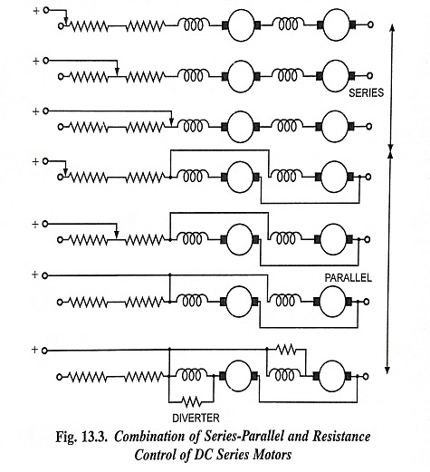
In the next step the two motors are connected in parallel and in series with a variable resistance R, as shown in Fig. 13.2 (c). This resistance is gradually cut out as the motors attain the speed and finally when this resistance is totally removed from the circuit, as illustrated in Fig. 13.2 (d), the second running position is obtained. In this position each motor is connected across the full line voltage. A diagram of connections illustrating the switching sequence is given in Fig. 13.3.
3. Field Control.
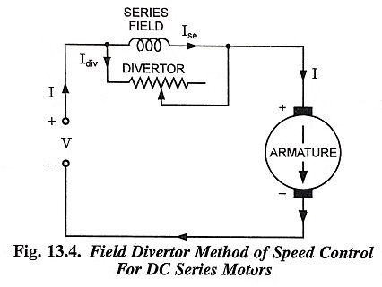
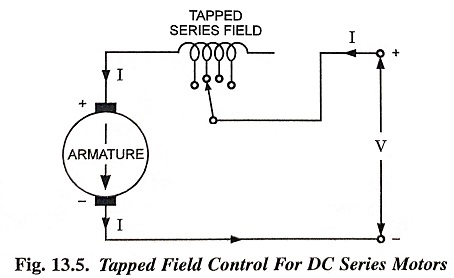
As the speed of the motor is inversely proportional to the flux (assuming line voltage constant), therefore, the speed can be varied by varying the flux. In case of series motors the flux can be varied either (i) by connecting a variable resistance known as diverter in parallel with the series field winding (refer to Fig. 13.4) or (ii) by cutting out some of the series field turns (refer to Fig. 13.5). Since in both the cases the flux can be only reduced, this method is known as field weakening method and speeds above normal can be obtained. By this method speed can be raised to the extent of 15 to 30 per cent of normal speed owing to design difficulties arising with traction motors.
The field weakening method is of no use for starting purpose. This method is used for increasing the speed of traction motors up to the extent of 10 or 15 per cent when they have attained maximum possible speed by series-parallel control system. The advantage of this system is that it increases the flexibility of the train utility.
For instance for city service, the speed required is low and frequent starting and stopping are required, the equipment can operate with the full field. When the same vehicle has to be employed for suburban and inter-urban lines where higher speeds are required, it would need a change in the gear ratio. By using field weakening method of speed control, the necessity of changing the gear ratio can be eliminated. Thus one type of equipment can be used to operate various types of services with a reasonable energy consumption.
4. Motor-Generator Locomotive Control
The motor-generator set usually consists of a single phase synchronous motor driving one or two dc generators and an exciter on the same shaft. The set is usually started and brought up to speed by a starting motor and automatically synchronised when it attains speed. The generator voltage is regulated by means of field control from exciter, therefore, neither resistance is required in traction motor supply circuit nor series-parallel control is required to obtain economical running speeds or save rheostat losses in the traction motor control. A series-parallel arrangement is sometimes used to permit economy in the size and weight of the generator.
5. Diesel Electric Locomotive Control
As already discussed earlier, diesel electric locomotive have come into prominence in the past few decades and have largely replaced steam locomotive, in many parts of the world. Primarily a diesel-electric drive, as used on locomotive, is a self-contained system of power conversion in which a diesel engine supplies power to the traction motors through a dc generator which it operates. Thus there are three fundamental parts in the diesel locomotive namely the diesel engine, the dc generator and the dc series traction motors.
The diesel engine drives the generator, and the generator supplies dc power to the traction motors, which in turn supply motive power to drive the vehicle. The field of the generator is indirectly excited by a battery the voltage of which may be varied by a rheostat. The battery voltage in turn varies the voltage of an auxiliary exciter or an amplidyne and this excites the main generator. The voltage of the generator is thus under control and this form of control makes unnecessary resistance grids in the main motor circuits to protect the traction motors in starting and accelerating. The engine speed is normally controlled by a load regulator which loads the engine according to the controller setting. This regulator automatically maintains a constant output, because if the engine demands more fuel than called for the setting, the regulator reduces field excitation and thus prevents stalling the engine. There are several types of diesel engine control, but they all in general follow this principle.